Add a new feature to a model (whitebox)
PRESENTATION
This tutorial is based on the previous tutorial: Add a new feature to a model (blackbox).
Prerequisites
Have done the previous tutorials Start to use Sim4Sys with a simple model (whitebox) and Add a new feature to a model (blackbox).
News skills that you will acquire
On Designer:
- Create imbricated states in a State Machine,
- Concept on entries,
- Use MinGW.
Duration
2h
START THE TUTORIAL
We can go into further details by splitting the service Turn Signal into more specific functions, as introduced in in the second tutorial for acceleration and braking. There are several ways of doing this according to your future project's needs. Here is an example of what functions can constitute our service. Here is an example:
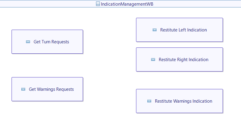
Keep in mind that the functions (White Box) and the service (Black Box) should keep the same logic, and the same mappings when visualizing. The White Box gives more details about how the Black Box works but should not change its behavior. However, don't go into too much details! In the function part, you should never use component related terms (example: light, steering wheel, comodo). In this part, we only talk about the functionalities, not how they should be applied.
In this example, the functions are the following:
- Get Turn Requests: to take into account all user's requests to activate or deactivate a turn signal.
- Get Warnings Requests: to take into account all user's requests related to warning activation.
- Restitute Left Indication: to handle the restitution of the left indication in any way (activation of external indication or feedback for the driver).
- Restitute Right Indication: to handle the restitution of the right indication in any way (activation of external indication or feedback for the driver).
- Restitute Warnings Indication: to handle the restitution of the warnings indication in any way (activation of external indication or feedback for the driver).
The_driver_requests_left_indication

- In the first part of the diagram, the request flow that we used in the service part is used again to go from the user to the function Get Turn Requests: each turn signal request goes into this function before any other. Here you will probably have to use the assistant as in Start to use Sim4Sys with a simple model (whitebox) to add the interface to this new function.
- You can see that the function has a current state which is Disengaged. Let's take a look at the Get Turn Requests state machine.
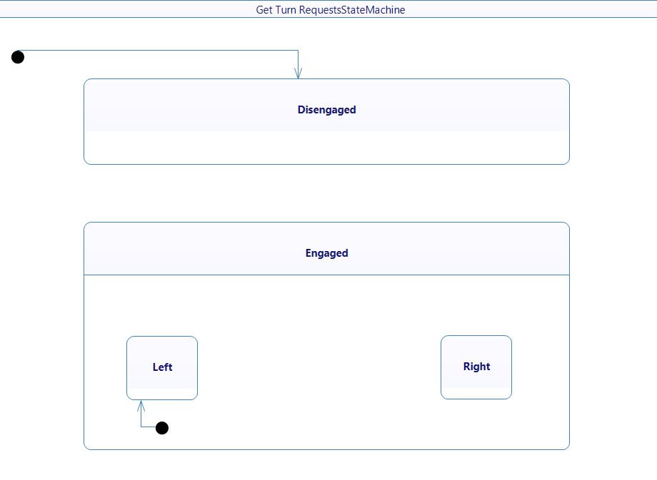
In this request function, we have the following states:
- Disengaged: to specify that no turn indication is currently requested.
- Engaged: to specify that a turn indication is currently requested by the user, regardless of the side engaged.
- Left: to specify that the left turn indication is requested.
- Right: to specify that the right turn indication is requested
Above is an example of imbricated states. To create this, you have to add a region element inside the Engaged state, which will allow you to drop other elements inside. Here you can add (or drag and drop) the Left and the Right state. You should also drop an initial point (black dot) inside this region so the state machine can know which state it should go to when entering the Engaged state, when Left or Right states are not specified.
Those states can be seen as the commodo next to the steering wheel of a car. However, you should not rely too much on a physical solution already, there are several ways of implementing a function on a system, and the commodo example is just one of them.
- In our case, the user wants to activate the left signal. This means that before the request, the state of the function Get Turn Requests must be Disengaged (and will be switched to Left then).

- Then, the flow is transmitted to the Restitute Left Indication function, here you will have to create a new interface with new flows. You can create an interface and flows as the example below:

- You can also see that the Restitute Left Indication function's state is Off. This is meant to express if the left indication is currently activated or not. Of course, by the end of the diagram, the state will be switched to On.
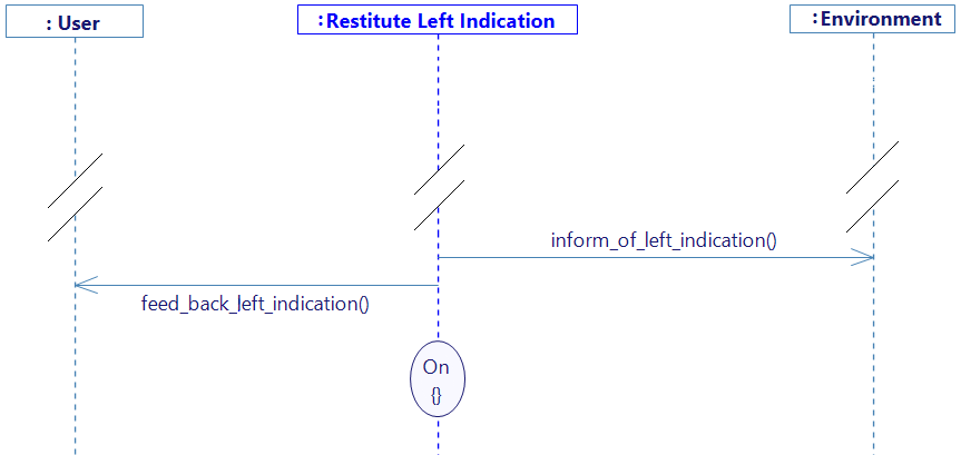
- The output flows previously existing in the service part is on this diagram too. They are both sent by the Restitute Left Indication function.
Remember that all output flows toward/from the environment or user, should match the Service part! When tracing the flow, select the existing one, and drag & drop the interface using the assistant, you can go back here for more information.
- At the end of the diagram, the state of the Resitute Left Indication goes from Off to On.
It is important that switching the state occurs at the end of this diagram, the behavior would not be exactly the same and could cause problems. If you switched state on a lifeline, and then, you trace a flow starting from this lifeline, it means that whenever we switch to this state again, it will trigger this flow automatically. The flow triggered is called an entry. It will act as a starting point every time we get into this state. Of course, this can sometimes be a desired behavior.
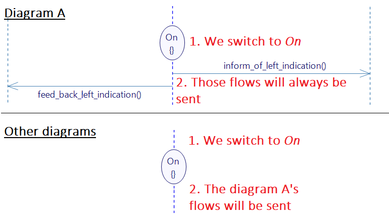
- Don't forget to also change the state of the Get Turn Requests signal, which should switch to the Left state at the end of the diagram too.
When it comes to the diagram The_driver_requests_right_indication, nothing changes but the names of the functions and flows you use.
The_driver_requests_to_stop_turning_indication
In the service part of this use case, we have decided that we would manage both turning indication when it comes to deactivation, instead of two diagrams.
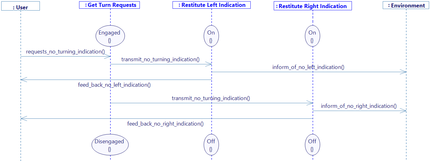
- As it is about both sides, we use the Restitute Left Indication and Restitute_Right_Indication.

- We first have a request flow, as previously. This flow is called requests_no_turning_indication and reaches the Get Turn Requests which is in the State of Engaged. Remember that this state covers both sub-states Left and Right. If it's one of the two, then it is also Engaged. This is one of the key principles which allows us to handle two cases in one diagram.
- Then we split our logic into two parts: one for each side. In the image above, we first handle the left part by sending a transmission flow to the Restitute Left Indication.
- We note that the initial state of Restitute Left Indication is On. We assume that the left indication part is activated. If we actually want to deactivate the right indication, then this function's state would be Off. As it is not represented in our diagram, the flow coming in will simply be ignored.
- We then send the output flows toward the environment and the user.
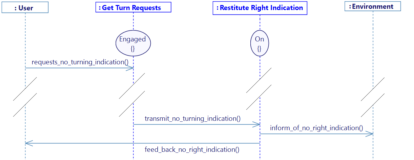
- Then another transmission flow is sent, but toward the Restitute Right Indication, to follow the same logic as just before but for the right side.

- At the end of the diagram, we change all the states that need to be changed:
- Engaged to Disengaged
- On to Off for both Restitute Indication functions.
The_driver_requests_warnings_indication
By following the same ways of creating the diagrams, we will see the The_driver_requests_warnings_indication, yet this one should be simpler than the previous once.

-
Here again, the user requests something. As it is related to warning activation/deactivation, the request goes through the Get Warnings Requests function. For this flow, as for previously, requests_warnings_indication must already exist from the Service part, because it goes from the user to our system, therefore, you will have to reuse the interface. There are no specific states in the request function: it is constantly Active.
-
Then the info is transmitted to Restitute Warnings Indication through transmit_warnings_indication. As for the Restitute Left/Right Indication, we also have a state here, switching between On and Off.
-
All output flows are sent as usual.
The_driver_requests_to_stop_warnings_indication

This diagram is very similar to the previous one. The only main change is the names of the flows carrying the opposite logic. Also, the state of the Restitute Warnings Indication is set to On, and is then switched to Off at the end of the diagram.
Switching from Service to Function
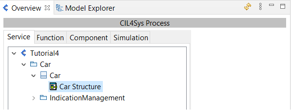
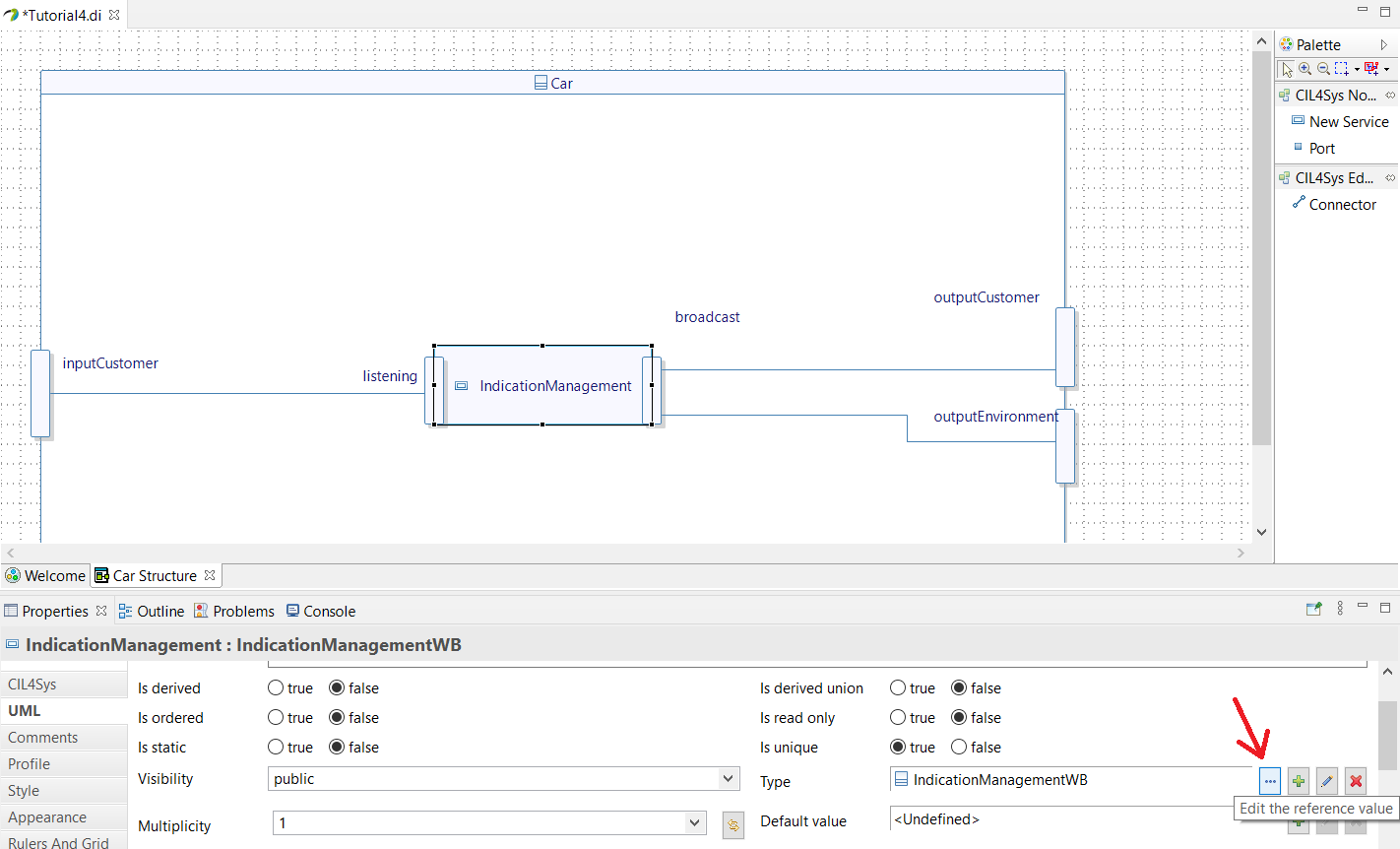
Before generating any code, remember that we need to specify to the software that we don't want to work with the service anymore, but with the functions. As a reminder, you need to go back into the service tab, and select the Car Structure diagram. Selecting the service, and going into the property tab, you can change the Type as shown below, to TurnSignalsWB (White Box) instead of TurnSignalsBB (Black Box).
Generation & Build
If you have the community version of Designer (free version), please build the executable via Hub4Sys as shown on this page.
For this project to work, you will probably need to follow the instructions here to compile using MinGW.
You can now generate & build your code. By launching your new executable, you should be able to run the visualization you've created before without changing any mapping. You just got into a deeper part of the process, and it should be the same logic. If it doesn't work as expected, it is a good way to see what can be wrong with the way you structured your functions. Once again, there are several ways of implementing the function of your service and it is up to you to create the architecture you want for your future project.