Start to use Sim4Sys with a simple model (whitebox)
PRESENTATION
This tutorial is based on the previous tutorial: Start to use Sim4Sys with a simple model (blackbox).
Retrieve the model of the previous tutorial (File > New > Example > Sim4Sys Examples > Sim4Sys – Quick Start > Tutorial 1) or continue your own model.
In this tutorial, we will be implementing the function part of the previous tutorial. The function part allows you to split the behavior of a service in more precise functions. Here we will be introducing one way of implementing it, however, keep in mind that it is not the only way.
Prerequisites
Have done the previous tutorial.
News skills that you will acquire
On Designer:
- Import an existing model,
- Create Functions (whitebox level),
- Complete a User Story at the functional level,
- Add Function Life Lines,
- Reuse a Service Level Interface,
- Use the Overview and the Assistant tabs,
- Move from a service level to a function level (and vice versa),
- Deal with two States or more in a State Machine.
Duration
2h
CREATE NEEDED FUNCTIONS
- Switch to the Function tab in the Overview

- Double Click on the structure diagram Speed_ManagementWB of the service to open it.
WB stands for "White Box", we will explain our service through functions, as opposite to BB, which stands for "Black Box", where all the logic is simplified as it was hidden.
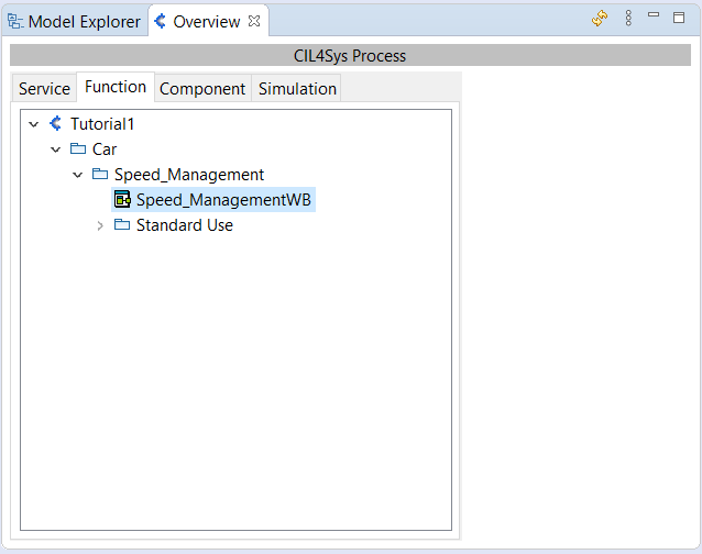
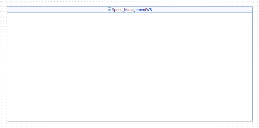
- Drag&Drop a New Function on the diagram
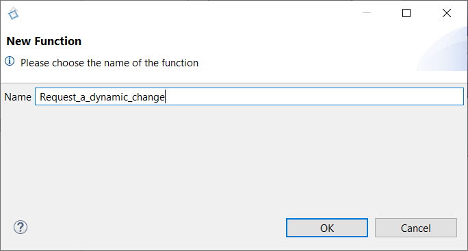
- Type the name of the new function: Request_a_dynamic_change
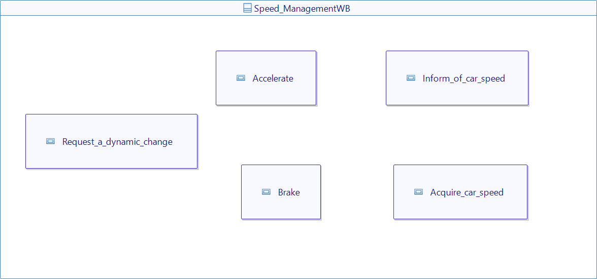
- Repeat the operation to create four other functions: Accelerate, Brake, Inform_of_car_speed, Acquire_car_speed.
User story "The driver accelerates_Analysed"
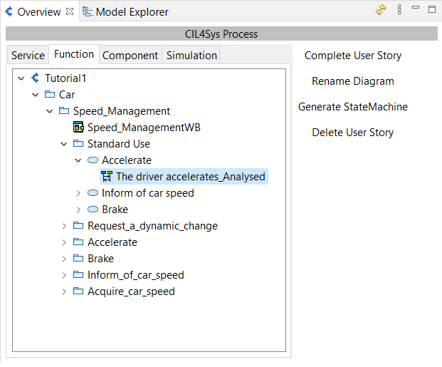
- Double Click on the user story The driver accelerates_Analysed in the Overview (Speed_Management > Standard Use > Accelerate) to open the corresponding sequence diagram
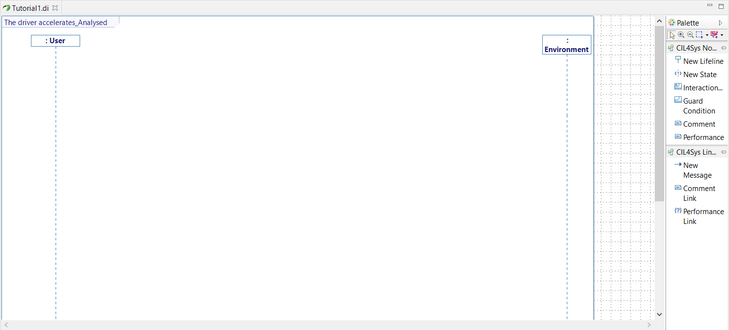
- Drag&Drop a New Lifeline on the diagram
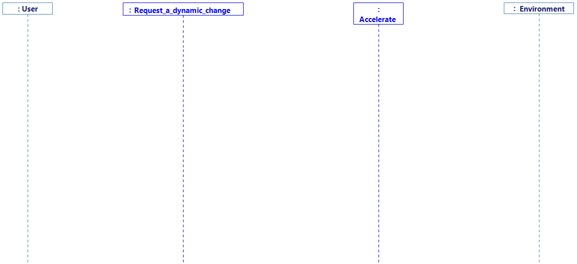
- Select Request_a_dynamic_change and Accelerate (by maintaining Ctrl).
- Click on Ok
- Arrange the diagram as follow by Dragging the lifelines
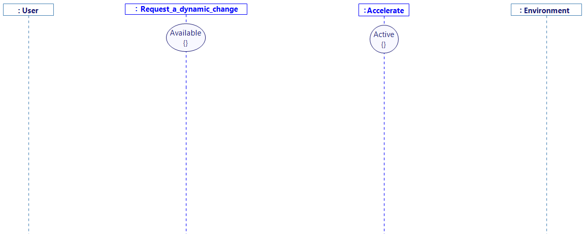
- Drag&Drop a New State on each function lifeline and rename them as follow
- Before anything, open the assistant tab (bottom-left corner), as shown:

The assistant tab is here to help you. Elements will automatically appear in this tab because you will probably need access to it. In our case, we will need to duplicate an existing interface from one function to another. To help you, the assistant will automatically keep a reference to this interface so you can use it easily.
- Drag&Drop a New Message between the user and the function Request_a_dynamic_change
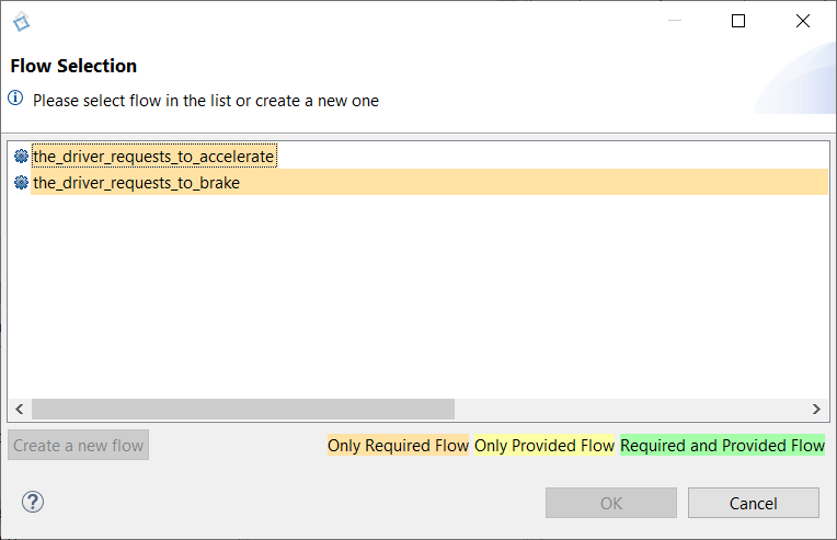
-
Select the_driver_requests_to_accelerate
-
Click on Ok
-
Read the dialog and the instructions (Be sure the Assistant View is open)

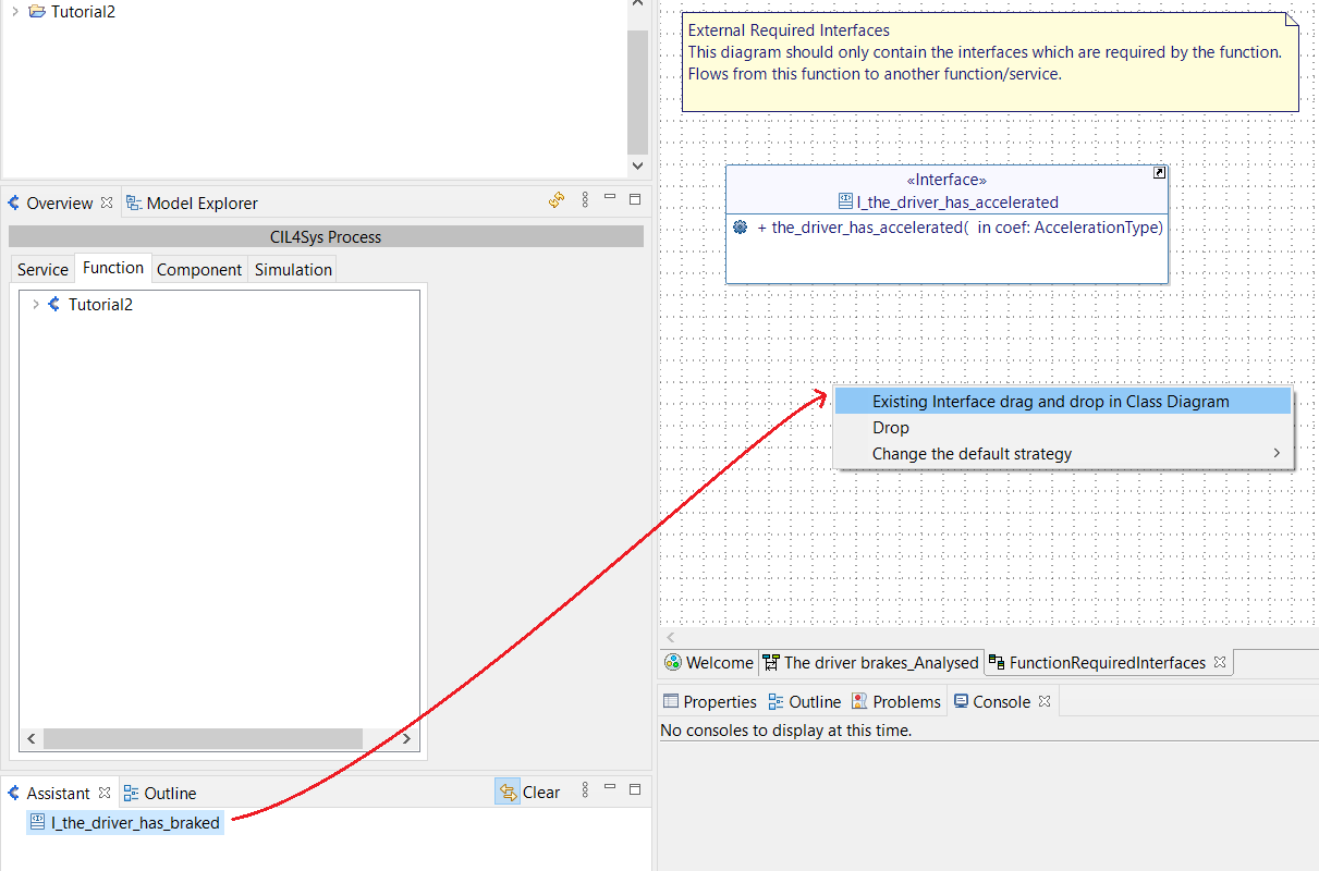
You can drag & drop a reference of an already existing interface, from the assistant tab.
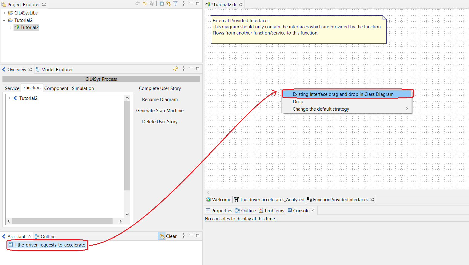
Here, the Assistant tab should display I_the_driver_requests_to_accelerate, an interface that you should use here.
- Drag&Drop the interface in the Class Diagram, and select the option Existing interface drag and drop in Class Diagram.
This step ensures that the function can realize the interface I_the_driver_requests_to_accelerate
In the next steps, the Assistant Tab will be used again. When using the assistant more than once, the previous elements are still there and can confuse you if you don't need them anymore. Therefore, you should clear the assistant by clicking on Clear.

-
Create an Interface I_the_driver_has_accelerated and a flow the_driver_has_accelerated (with an argument value whose name is coef and type is AccelerationType) between Request_a_dynamic_change and Accelerate and trace it on the analysed user story.
-
Drag&Drop the newly created interface I_the_driver_has_accelerated in the Class Diagram FunctionRequiredInterfaces from the Assistant tab, as you have done before.
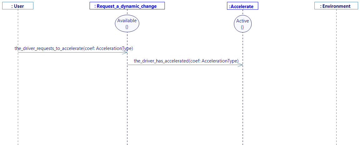
- Create an intern activity named compute_acceleration on Accelerate
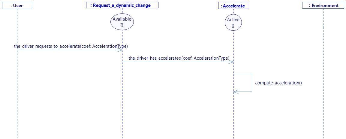
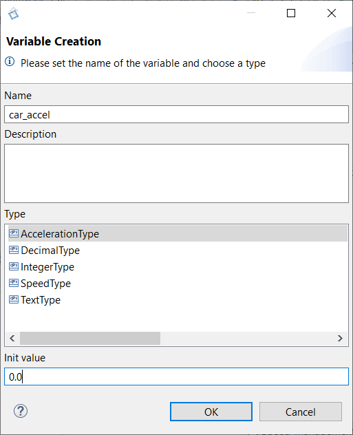
- Create a Variable car_accel with type AccelerationType in the function Accelerate and set value to 0.0 (right click on the “Accelerate” lifeline, or on the compute_acceleration intern activity, and select Edit -> Create Variable)
-
Trace a New Message between the function Accelerate and the environment.
-
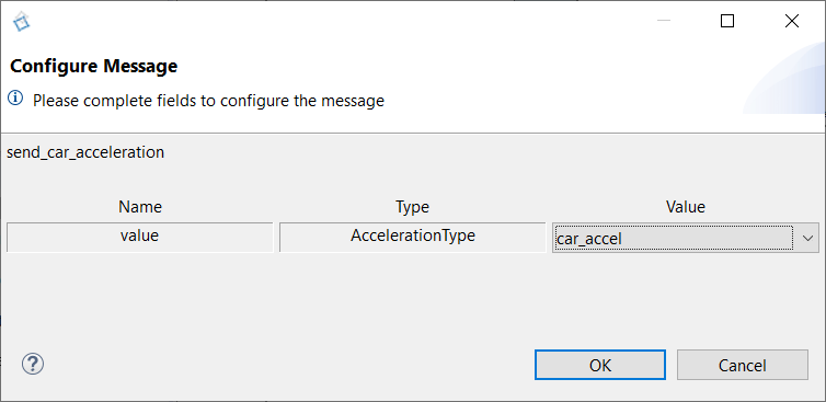
Select the flow send_car_acceleration and select car_accel on the value field.
-
As done before, Drag&Drop the interface I_send_car_acceleration in the Class Diagram from the Assistant tab.
-
Complete the internal activity compute_acceleration (Right click on the activity then select Edit -> Complete Activity):
car_accel = the_driver_has_accelerated_coef;
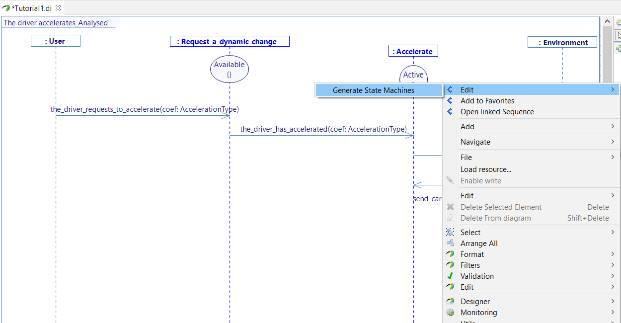
- Generate the state machines
- Select the diagram in the overview and click on Generate StateMachine
- OR Right click on the diagram and Select > Generate > Generate State Machine
User story "The driver is informed of the car speed_Analysed"
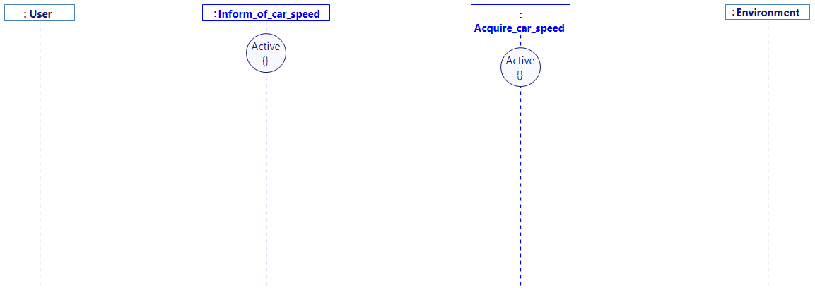
- Double Click on the user story The driver is informed of the car speed_Analysed in the Overview (Speed_Management > Standard Use > Inform of car speed) to open the corresponding sequence diagram
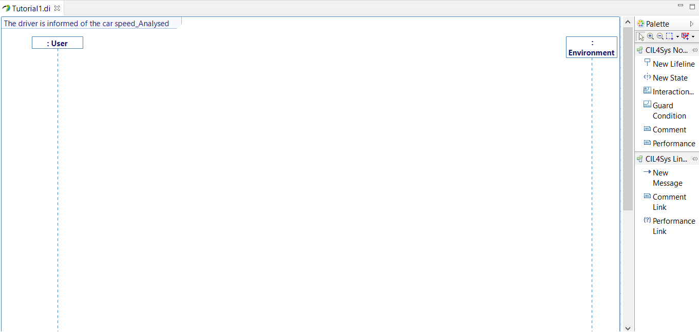
- Drag&Drop a New Lifeline on the diagram
- Select both Inform_of_car_speed and Acquire_car_speed (holding Ctrl)
- Click on Ok
- Drag&Drop a New State on both lifelines that you can rename "Active"
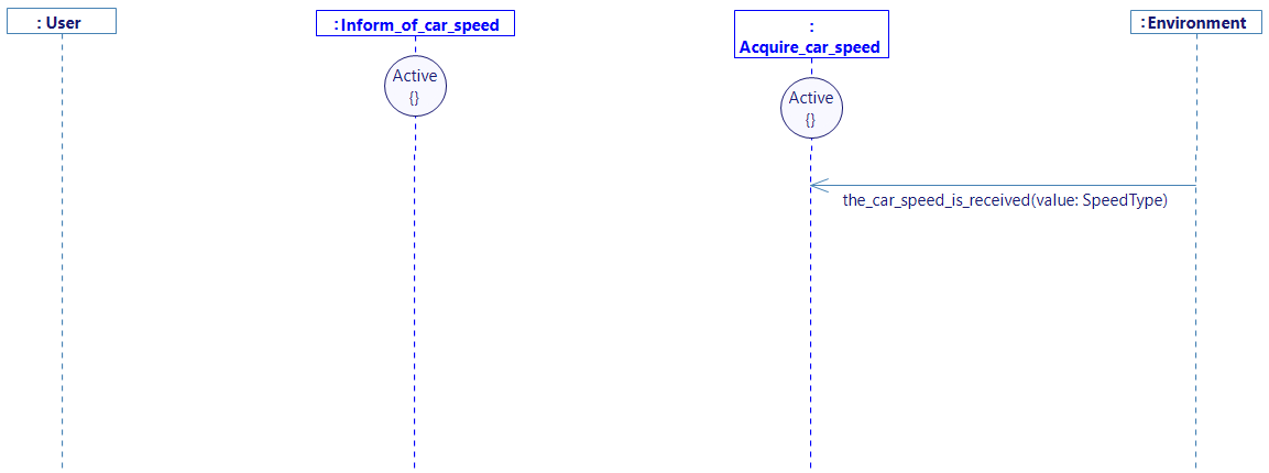
- Trace a New Message between the environment and the function Acquire_car_speed
- Select the_car_speed_is_received
- Click on Ok
- Drag&Drop the interface I_the_car_speed_is_received in the Class Diagram, from the Assistant tab.
- Trace a New Message between the function Acquire_car_speed and Inform_of_car_speed, and click on Create a new flow
- Create a new interface, and name it I_transmit_car_speed
- In this interface, add a flow whose name is transmit_car_speed, with a parameter called value of type SpeedType.
- Trace this flow on the sequence diagram, select the_car_speed_is_received_value as transmitted value by this flow, and drag&drop the needed interface as done before.
Now, let's send the speed information to the user:
- Trace a New Message between the function Inform_of_car_speed and the user
- Select the flow inform_the_driver_of_the_car_speed, with transmit_car_speed_value as transmitted value.
- Click on Ok
- Drag&Drop the interface I_inform_the_driver_of_the_car_speed in the Class Diagram, from the Assistant tab.

- Generate the state machine.
As the same mapping is used for the visualization, only the level of visualization (Service or Function) must be specified.
SWITCH BETWEEN SERVICE VISUALIZATION AND FUNCTION VISUALIZATION
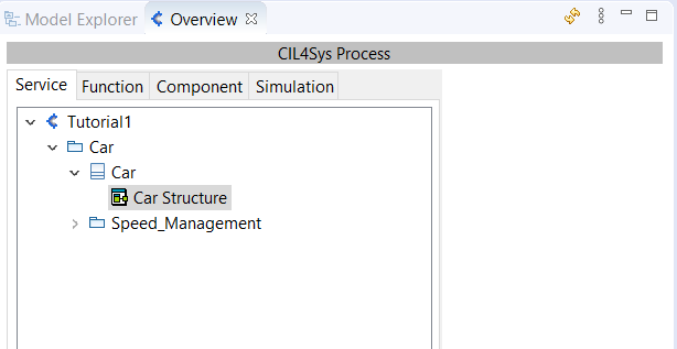
- Go back to Service tab in the Overview,
-
Open the structure diagram of the Product (the one named Car Structure),
-
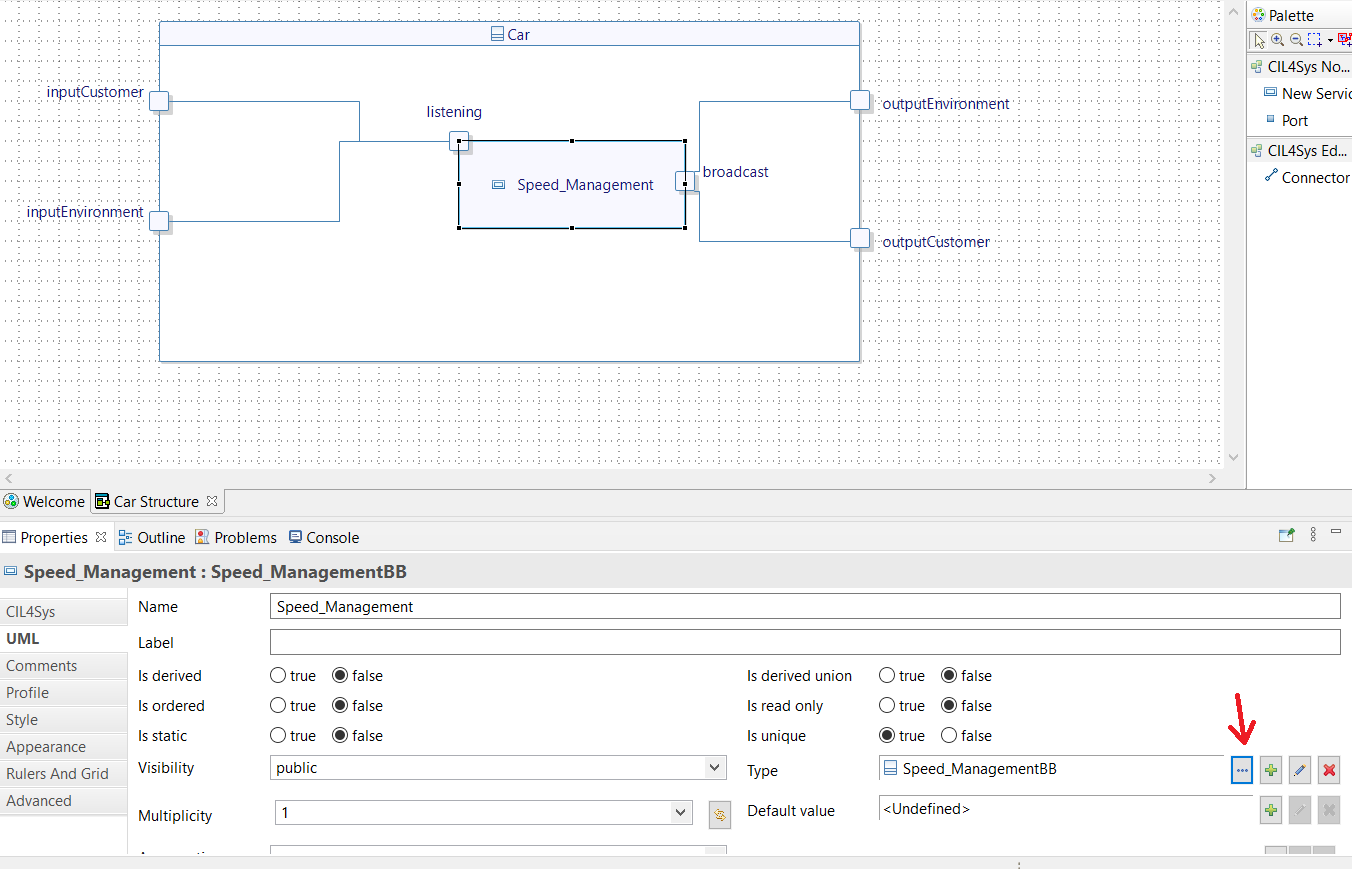
Select the Speed_Management Service box,
-
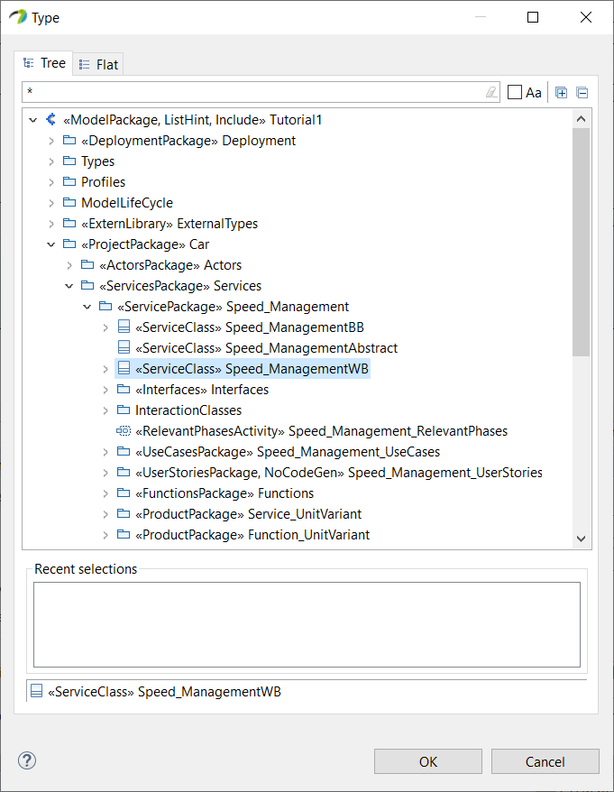
Highlight the Properties view (bottom right of the window) and set the "Type" of the service on Speed_ManagementWB (WB for WhiteBox):
- Come back to the function tab, so you don't forget to work on the right level of visualization.
NOW LET'S DO THE SAME THING FOR THE BRAKE FUNCTION
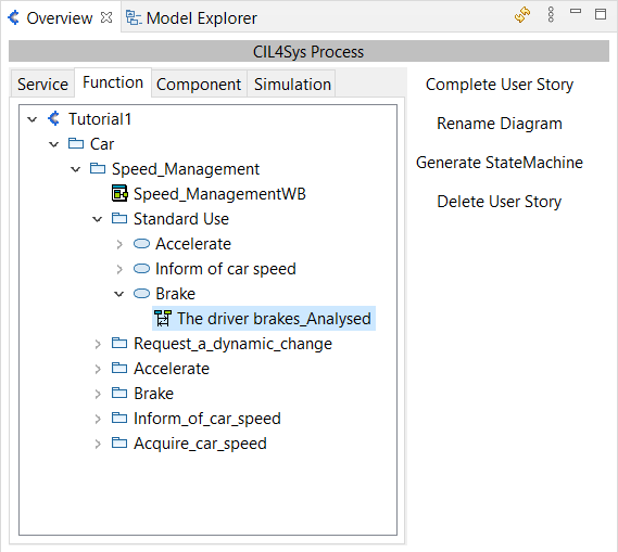
- Double Click on the user story The driver brakes_Analysed in the Overview (Speed_Management > Standard Use > Brake) to open the corresponding sequence diagram
- Drag&Drop a New Lifeline on the diagram
- Select Request_a_dynamic_change, Brake and Acquire_car_speed (by holding Ctrl).
- Click on Ok
- Arrange the diagram as follow by dragging the lifelines

- Drag&Drop a New State on each function lifeline

In this part we will need to access the speed of the vehicle. Remember that we've previously acquired the speed thanks to a flow (that will be continuously sent by the visualization) between the environment and the function Acquire_car_speed. We're going to trace the same process again, to add the transmission of the speed to the Brake function, triggered by the acquisition of the car speed.
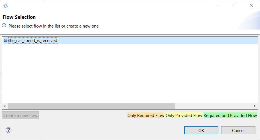
- Trace a New Message between the environment and the function Acquire_car_speed and select the_car_speed_is_received as used before.
-
Trace a message between Acquire_car_speed and Brake, and use the same transmit_car_speed flow as before too, with the_car_speed_is_received_value as transmitted value.
-
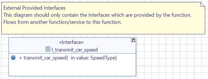
The already existing interface will need to be drag&dropped from the Assistant tab.
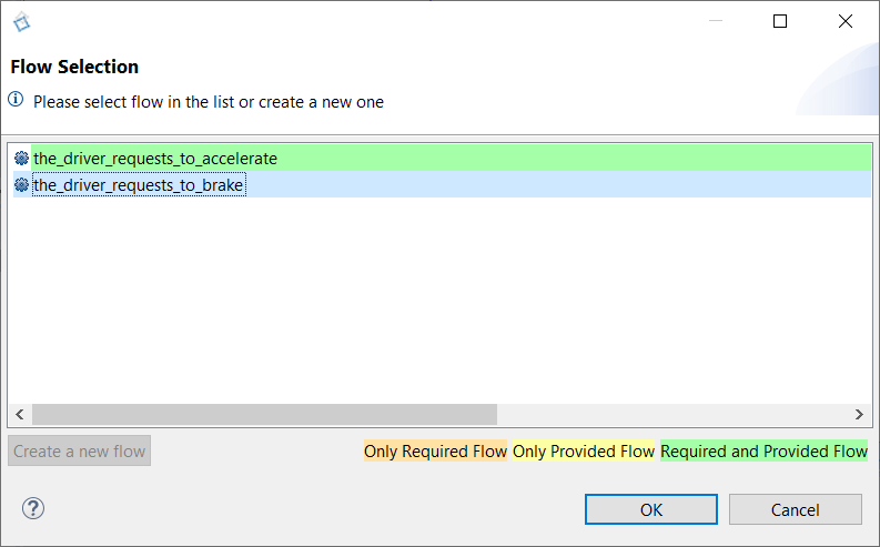
- Trace a new Message between the user and the function Request_a_dynamic_change
-
Select the_driver_requests_to_brake and Click Ok
-
Drag&Drop the interface I_the_driver_requests_to_brake in the Class Diagram, from the Assistant tab.
-
Trace a new message between Request_a_dynamic_change and Brake
-
Create a new Interface I_the_driver_has_braked and create a new Flow the_driver_has_braked with an argument value whose name is coef and type is AccelerationType
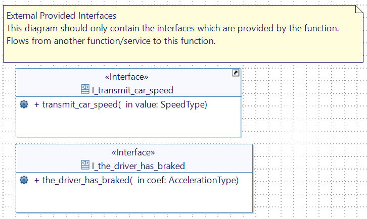
- Trace the newly created flow between Request_a_dynamic_change and Brake on the analysed user story, with the_driver_requests_to_brake_coef as transmitted value
- Drag&Drop the Interface I_the_driver_has_braked from CIL4Sys Assistant to the FunctionRequiredInterface
- Create an internal Activity named compute_deceleration on Brake
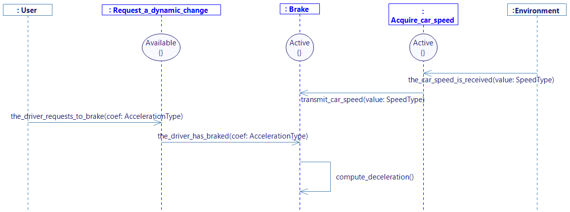
- Create a Variable car_accel with type AccelerationType in the function Brake and set value to 0.0 (Right click on the Lifeline Brake and select Edit -> Create Variable)
- Complete the internal activity compute_deceleration (Right click on the activity then select Edit -> Complete Activity):
car_accel = the_driver_has_braked_coef;
-
Trace a New Message between the function Brake and the environment.
-
Select the flow send_car_acceleration and select car_accel on the value field, as done before with the Accelerate function.
-
Drag&Drop the interface I_send_car_acceleration in the Class Diagram from the Assistant tab.
-
Create a new constant in the Brake function (right click on the function Edit -> Create Constant) called NULL_SPEED, of type SpeedType and set value to 0.0.
-
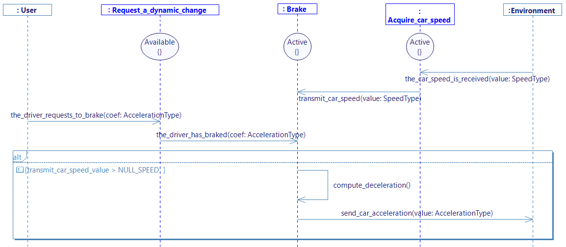
Create a Guard Condition on the analysed user story
-
Select the trigger of the guard condition: the_driver_has_braked(the_driver_requests_to_brake_coef).
-
Set the condition as followed:
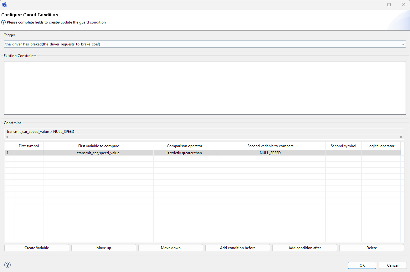
You should obtain a diagram like the following one :
Now, repeat the same process but with a different guard condition, handling the opposite condition:
Before creating the guard condition, you should trace a new message between User and Request_a_dynamic_change and between Request_a_dynamic_change and Brake. If you do so, the correct trigger will be available at the creation of the guard condition.
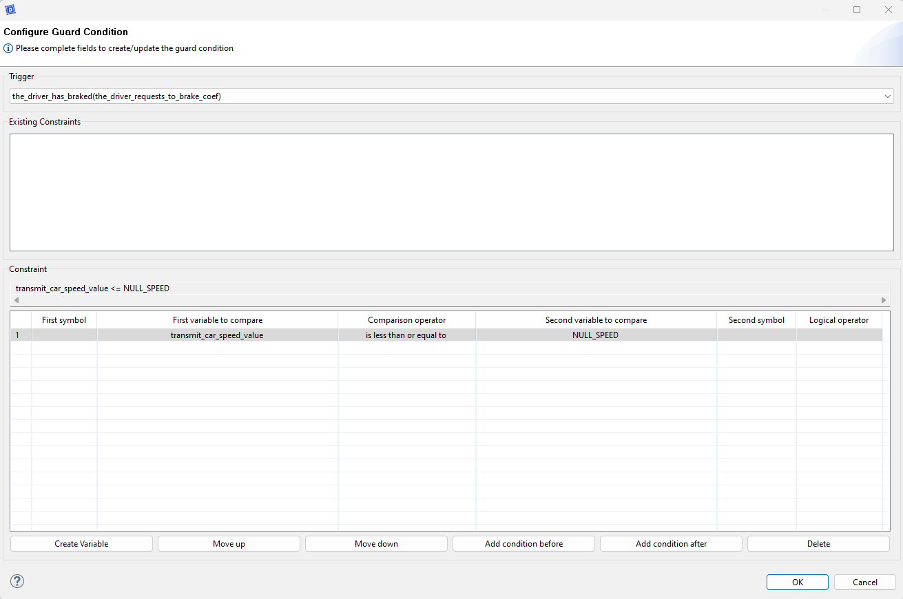
You should obtain this:

- Create a new internal activity in the Brake function and call it set_acceleration_value_to_zero
- Complete the internal activity as follow :
car_accel = NULL_SPEED;
- Then finish the diagram with send_car_acceleration as previously done with the first guard condition. You should obtain a diagram like this :
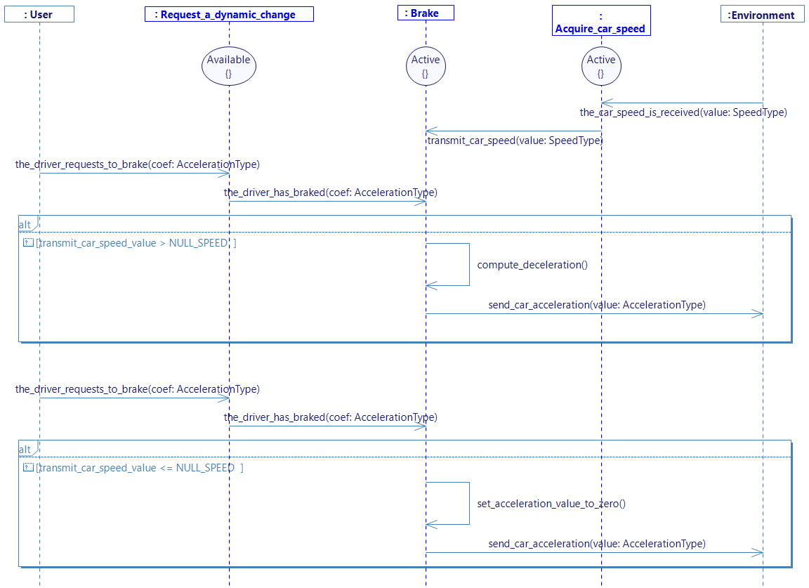
To increase the size of the different lifelines,and be able to draw more sequences, you can select all of them, select the balck square at the bottom of one of the lifeline then pull it down.
- Generate the state machines
- Select the diagram in the overview and click on Generate State Machine
- OR Right click on the diagram and Select > Edit > Generate State Machine
GENERATE CODE
If you have the community version of Designer (free version), please build the executable via Hub4Sys as shown on this page.
- Click on Generate code in CIL4Sys Overview
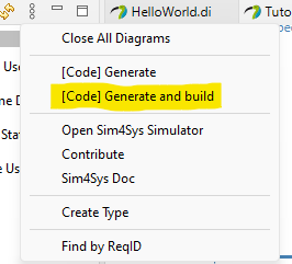
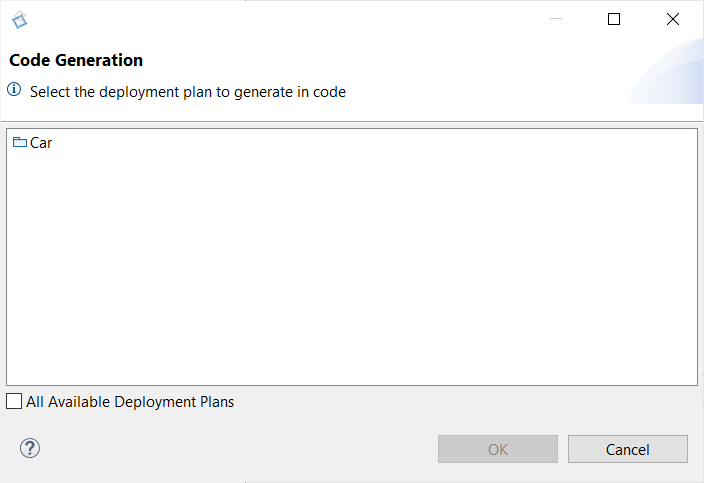
- Select Car
- Click on OK
- Select Cygwin GCC (Cygwin 64 must be installed, for Windows only)
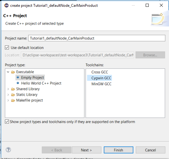
- Click on Finish
- Click on OK in the confirmation dialog box
Building using cygwin is easier to set up, however, it seems that the stability of the executables can sometimes cause issues (e.g. the executable stops working right after it is launched) That is why it is often better to build using the minGW parameters on this link.
- Right Click on the newly created C++ project
- Select Build Project
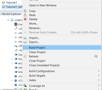
- Right Click on the C++ project
- Select RunAs > C/C++ Application
- Go to the Sim4Sys Virtual Bench: https://sim4sys.com/
- Re-open the exact same project as for previous tutorial.
The mapping should not be changed! The goal here is to have the same behavior even though you got deeper into the function part.
-
Connect the executable with the visualization with the WebSocket button in the top right (
 to
to  ).
). -
Play the visualization
The gauge should increase, decrease, and then stop at 0. On the scene2D context, the car should start moving while the speed increases and then slow until complete stop during the braking phase.