Add a new feature to a model (blackbox)
PRESENTATION
This tutorial can be done in an existing model of car or in a new model (the creation of the model and the project is not presented in this tutorial).
Prerequisites
Have done the previous tutorial: Start to use Sim4Sys with a simple model (whitebox).
News skills that you will acquire
On Virtual Bench:
- Create a HMI Enumeration,
- Use a new Context elements: Commodo, Light signal equipment, Blinking picto,
- Attach an element to another.
Duration
3h
CREATE A NEW SERVICE
- Go into the Project’s structure diagram
- Create a New Service named IndicationManagement, in the composite structure diagram of the product you are specifying


- You should have the following elements: (refresh if all of them don't appear yet)

- Add the life phase “Standard Use” to the Life Phase diagram

USE CASES
- Create an User actor named Driver (you can rename it at its creation, or via its Properties view), in the Use Case Diagram (UCD)
- Create the following use cases of the life phase “Standard Use” and associations between them and Driver:
- Activate_Left_Indication
- Activate_Right_Indication
- Deactivate_Turning_Indication
- Activate_Warnings_Indication
- Deactivate_Warnings_Indication

STORIES
For the following use cases, you will have to create user stories as below:

-
Create the following user story in the use case Activate_Left_Indication:
- The_driver_requests_left_indication
-
Create the following user story in the use case Activate_Right_Indication:
- The_driver_requests_right_indication
-
Create the following user story in the use case Deactivate_Turning_Indication:
- The_driver_requests_to_stop_turning_indication
-
Create the following user story in the use case Activate_Warnings_Indication:
- The_driver_requests_warnings_indication
-
Create the following user story in the use case Deactivate_Warnings_Indication:
- The_driver_requests_to_stop_warnings_indication
REQUEST FLOWS AND INTERFACES
- Open the Request Interfaces diagram.

In this diagram, you will need to specify the interfaces requested from the user.
- You can organize the interfaces and flows as follow:
- I_request_turning_indication
- requests_left_indication
- request_right_indication
- requests_no_turning_indication
- I_request_warnings_indication
- requests_warnings_indication
- requests_no_warnings_indication
- I_request_turning_indication

FEEDBACK FLOWS AND INTERFACES
-
Open the Feedback Interfaces diagram.
-
Here you specify the interfaces provided to the user as feedback from the service:
- I_feed_back_turning_indication
- feed_back_left_indication
- feed_back_right_indication
- feed_back_no_left_indication
- feed_back_no_right_indication
- I_feed_back_warnings_indication
- feed_back_warnings_indication
- feed_back_no_warnings_indication
- I_feed_back_turning_indication

FLOW AND INTERFACES TO ENVIRONMENT
-
Open the ToEnv diagram.
-
Interfaces going to the environment are specified there:
- I_inform_of_turning_indication
- inform_of_left_indication
- inform_of_right_indication
- inform_of_no_left_indication
- inform_of_no_right_indication
- I_inform_of_warnings_indication
- inform_of_warnings_indication
- inform_of_no_warnings_indication
- I_inform_of_turning_indication

TURNING SIDE TYPE
We will need to create a type that can express the side requested by the user. It will be an enumeration with three possible values: Left / None / Right.
-
Go to the Type diagram and create a new Enumeration called TurnSideState.

-
Drag&drop three New Enumeration Literals on the title compartement and named them Left, None, and Right.

FILL ALL THE SEQUENCE DIAGRAMS
Activate_Left_Indication
The_driver_requests_left_indication
The first flow is a request from the user. By its name, it is holding the information that the request is to activate the left indication. A variable has been added to the lifeline. It is called engaged_turn_side and its type is the one created just before: TurnSideState and its default value is None. This value will allow us to memorize that last request of the user. In our service, we want the user to be able to choose the turning side, but we don't want to be able to activate the right indication while the left indication is still going on. This will help us manage this case. The indication must be turned off before requesting a new side.

- Before activating the left signal, we make sure that the current indication is off, thanks to a condition guard with the following condition:
engaged_turn_side == None. If the condition is true, we go on to the next step. - An activity that you can name engage_left, will allow us to change the engaged_turn_side variable to its new value: Left.
Remember that you can easily change a variable's value in an activity with a Right-Click on it > Edit > Complete Activity > Set Default Values. Here you can choose the variable you want to change, and the value you want to attribute.
- To finish, a flow will inform the environment, and another one will inform the user with feedback.
Activate_Right_Indication
The_driver_requests_right_indication

The same logic goes for this diagram. A condition guard is still needed to make sure that no turn side is engaged yet. Then another activity called engage_right switch the value of engaged_turn_side to Right. Make sure you don't forget to complete the activity. Then both output flows are sent as the previous one.
Deactivate_turning_indication
The_driver_requests_to_stop_turning_indication
Here we have decided that one diagram would be enough to describe a deactivation, for both left and right.

- The guard condition here is a bit different:
engaged_turn_side != Nonewhich means that we can be in any case as long as the indication is not already disengaged. (As long as engaged_turn_side is different from None). - To ensure that we manage both cases, we send output flows for both the left side, and the right side.
Activate_Warnings_Indication
The_driver_requests_warnings_indication

For the warnings to work properly, it is even simplier. The request flow is just followed by the two output flows.
Deactivate_Warnings_Indication
The_driver_requests_to_stop_warnings_indication

For the warnings deactivation, the same logic is applied.
GENERATE CODE
Make sure you are in the Service Simulation level.
State Machine Generation
Once you have generated the state machine for each sequence, you should have the StateMachine diagram for the service TurnSignals (after rearranging it) as follows:

Next, proceed to generate the code and export the XML file.
If you have the community version of Designer (free version), please build the executable via Hub4Sys as shown on this page.
CONTROLLERS – SIGNALS
-
Go on the Sim4Sys Virtual Bench: https://sim4sys.com/
-
Identify: with your login and password
-
Create a new Model :
-
Import types and flows from the model to the virtual bench by following the steps in this paragraph.
-
Add a model instance linked to the model, in the Model instances tab.
-
Copy your existing scenario from the first tutorial or Create a new one.

-
Name it TurnSignalScenario
-
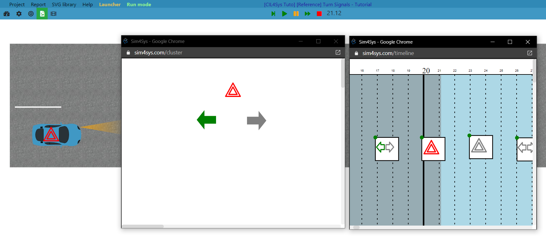
Open Scene2D environment and Drag/Drop elements as the following picture.

Simulation to model mapping
We offer you different ways to realize your simu to model mappings, for example:
- via the timeline
- via commodos
- via HTML buttons
Here we will map the flows with the timeline.
Using the timeline
Create HMI enumeration
- In the Resources tab, create one HMI enumeration by clicking on New.

- Then, create your HMI enumeration to have an enumeration. The first button (Pen) allows to edit SVG definition and the second button (list icon) allows you to load SVG images already created (Find more information here).

Set the timeline
Within the Timeline context, the Timeline events axis is already pre-existing.
Then place as many Timeline action trigger as you want for your scenario.

Create controllers corresponding to the activation or deactivation of each indicator.
To do this, select each timeline action and create a new controller from the Triggered Controllers section
Read the following pages : controllers overview, controllers management, and other controller dedicated pages if you have troubles with controllers.

Do the same for the deactivation (OFF) request and the right ON request.
For the second deactivation request timeline action, you can select reuse and select the deactivation request controller created previously
Using commodos
If you want to send the commands yourself, you are not limited to using the timeline. In this part, we will see how you can also implement the mapping using commodos. However, keep in mind that there are a lot of other ways too.
- Drag & drop a commodo element in your Command context:

- In the Side View, define its State field to the HMI Enumeration turnSignal and state off (it will be the default position at the beginning of the Run):

If you only have 1 HMI enumeration "turnSignal" in your project, it will be selected by default when you drop a Commodo element
- Then, right click on it and select Controllers -> Trigger a controller:

- Click on Create
- Add the turnSignal model lifeline
- Add 1 action towards the turnSignal model lifeline with the flow requests_left_indication :
- Add a condition : commodo state == turnSignal Left

Now, when you change the commodo to the left position, the flow requests_left_indication will be sent.
- Do the same steps with flows requests_right_indication and requests_no_turning_indication. For warnings flows, add a second commodo with "driverAction" to "warning".
Using HTML Buttons
-
Drag & drop a button into a Command HMI environment and assign a name.
-
Create a controller from the button element with its event (in this example, we'll use the 'Released' event) that will send the flow requests_left_indication.
-
Follow these steps again for the flows requests_right_indication and requests_no_turning_indication.
Model to simulation mapping
Here we decide to inform the environment if signals were on or off.
- Switch to Scene2D Context.
Use two Light Signals as follows and place it on your car.

-
Attach the lights to the car.
-
Choose correct parameters for Light Signal objects (X-axis relative position = 1.3m and Y-axis relative position = +/- 0.5m here) to place it as follow:

- Create and apply Light Signal controllers to the correct Light Signal element. For instance:

- For now, we don't specify the fact that activating the warnings obviously means that both turning signals are on. This is a choice that will be made later. In the service part, we just tell that we want to indicate the driver's requests. If you want to map the warnings, you can just add a warning element that will be switched on and off. For example, a picto generic element.
Make it work
- Switch to Run Mode.
- While your papyrus project is running, connect the WebSocket by clicking on it (the red button in the top right).
- There are several ways to make it work, you could even use HTML buttons, and witness the scene from a 3D point of view.