Hello World
PRESENTATION
Embark on your MBSE journey by learning to model and visualize your first system with Papyrus, laying the groundwork for your exploration into complex systems engineering, where your first model and visualization await to bring theory to vivid life.
Prerequisites
Ensure your workstation is set up with Designer, Launcher, and Cygwin installed to fully engage with the modeling and visualization process.
Skills that you will acquire
On Designer:
- Create a Model, a Project and a Service,
- Add a Life Phase to a Service,
- Create a Use Case and a User Story in this former,
- Complete a User Story with flow and interfaces, internal activities,
- Generate State Machine from User Stories and an associated C++ Code, as an executable,
- Export a XML contening Types and Flows created in your model.
On Virtual Bench:
- Login on Virtual Bench,
- Import Types and Flows,
- Create a Project and add Contexts in it (HMI, Scene2D and Timeline),
- Add a New Scenario,
- Use Context elements (Timeline action, Test Criteria, Text),
- Add Executable Instance,
- Add mappings between the bench and your model,
- Run your Scenario.
Duration
1h
MODELISATION ON DESIGNER
Create a Model
- Papyrus
- Rhapsody
Start your model by establishing a new Designer project, selecting the CIL4SysLanguage for systems engineering.
- Click on File > New > Papyrus Project

- Select CIL4SysLanguage checkbox
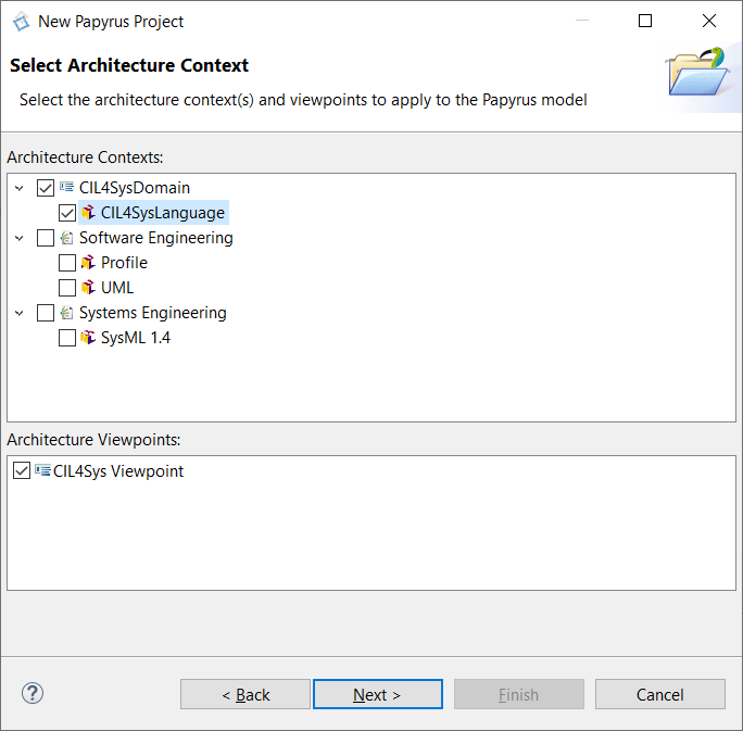
- Click on Next
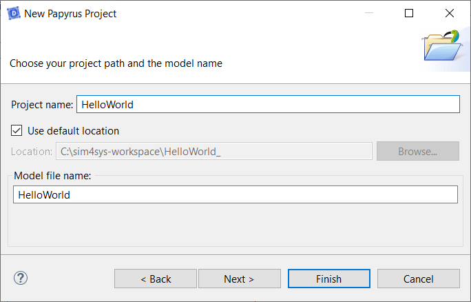
- Type the name of the Papyrus Project: HelloWorld, in the project name field
Please ensure that there are no spaces in your model name.
- Click on Next
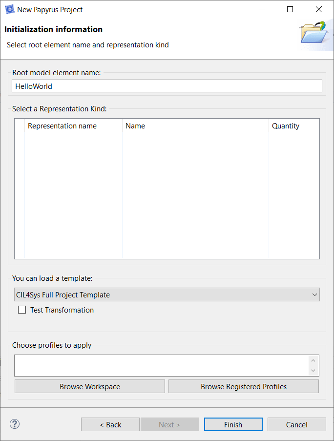
- Select CIL4Sys Full Project Template in the field: “You can load a template”
- Click on Finish
- Click on File > New

- Type the name of the project: HelloWorld
- Click on OK
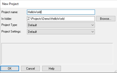
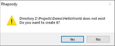
- Rhapsody will ask you if you want to create a new folder for the project, Click on Yes
Create a Project
- Papyrus
- Rhapsody
Define your system's scope by creating a new project within Papyrus, preparing yourself for detailed modeling.
- Select HelloWorld in CIL4Sys Overview. You can use the Refresh View button when selecting the Overview tab.

- Click on New Project

Sometimes, the button does not appear because of the size of the window. You can either resize the Overview tab horizontally or use a bigger screen.
- Type the name of the project: MyProject
Please ensure that there are no spaces in your model name.
- Click on OK
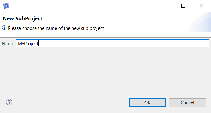
- Click on Ok in the confirmation dialog box
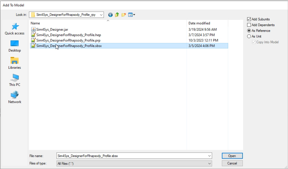
- Click on File > Add To Model

- Choose the file called Sim4Sys_DesignerForRhapsody_Profile.sbsx
- Click on Open
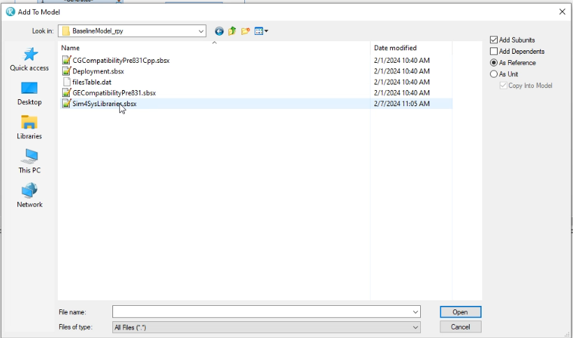
- Click on File > Add To Model
- Choose the file called Sim4SysLibraries.sbsx
- Click on Open
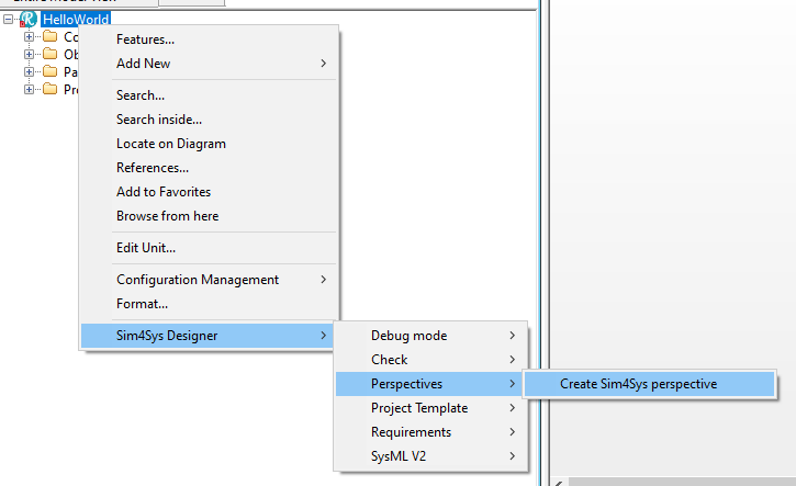
- Right Click on the Project
- Click on Sim4Sys Designer > Perspectives > Create Sim4Sys perspective
- Click on the Sim4Sys Perspective on the Toolbar
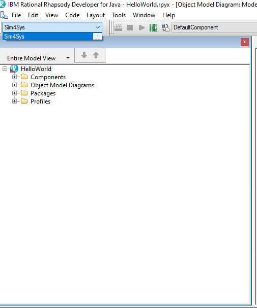
Even if the perspective is selected click on it again, sometime Rhapsody doesn't use the perspective even if it is selected.
Create a Service MySpec
- Papyrus
- Rhapsody
Action: Add a service named "MySpec" to the model.
Explanation: We are adding the 'MySpec' service to represent a key functionality of our system, such as user management. This service is crucial because it defines how users interact with our system, directly influencing the user experience and the system's security.
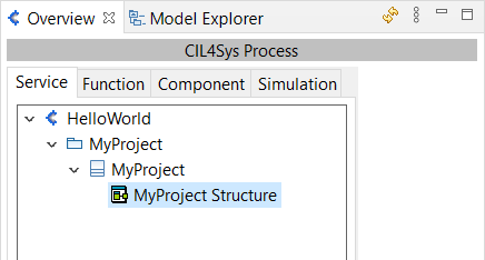
- Double Click on the MyProject Structure diagram. This will open the product composite structure diagram (CSD).
- You can resize the composite structure diagram by dragging the corners.
- Composite Structure Diagrams allow the users to "Peek Inside" a product to see exactly what it is composed of.
- Drag&Drop a New Service in the product CSD (the large box with the name of the product)
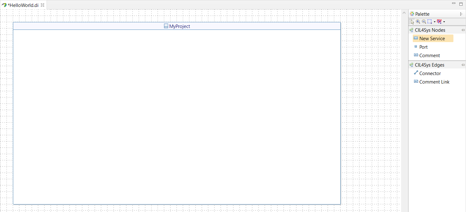
- Select Create
- Type the name of the service: MySpec
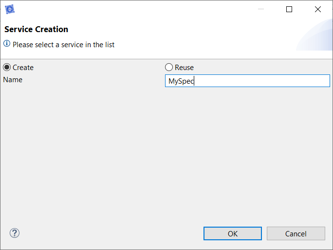
- Click on OK
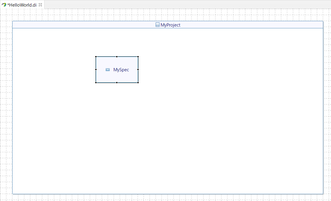
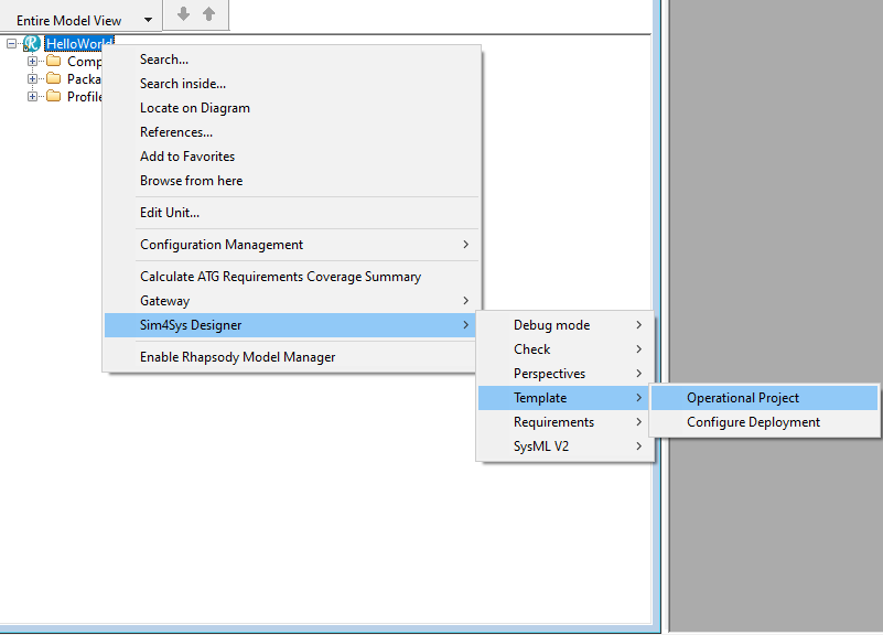
- Right Click on the Project
- Click on Sim4Sys Designer > Template > Operational Project
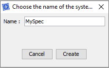
- Type the name of the attribute: MySpec
- Click on Create
Add a Life Phase to a Service
- Papyrus
- Rhapsody
Action: *Define a lifecycle phase "Standard Use" for a service. *
Explanation: By specifying a 'Standard Use' lifecycle phase, we clarify the normal conditions under which this service is supposed to operate. This helps us model expected behaviors and prepare the system for robustness testing by visualizing real usage conditions.
By default, we suggest you two different phases: Standard Use and Visualization.
- Select MySpec Package in CIL4Sys Overview (refresh if it does not appear).
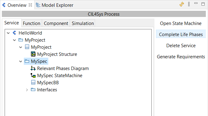
- Click on Complete Life Phases
- Drag&Drop a New Life Phase in the diagram pane for relevant phases of the service
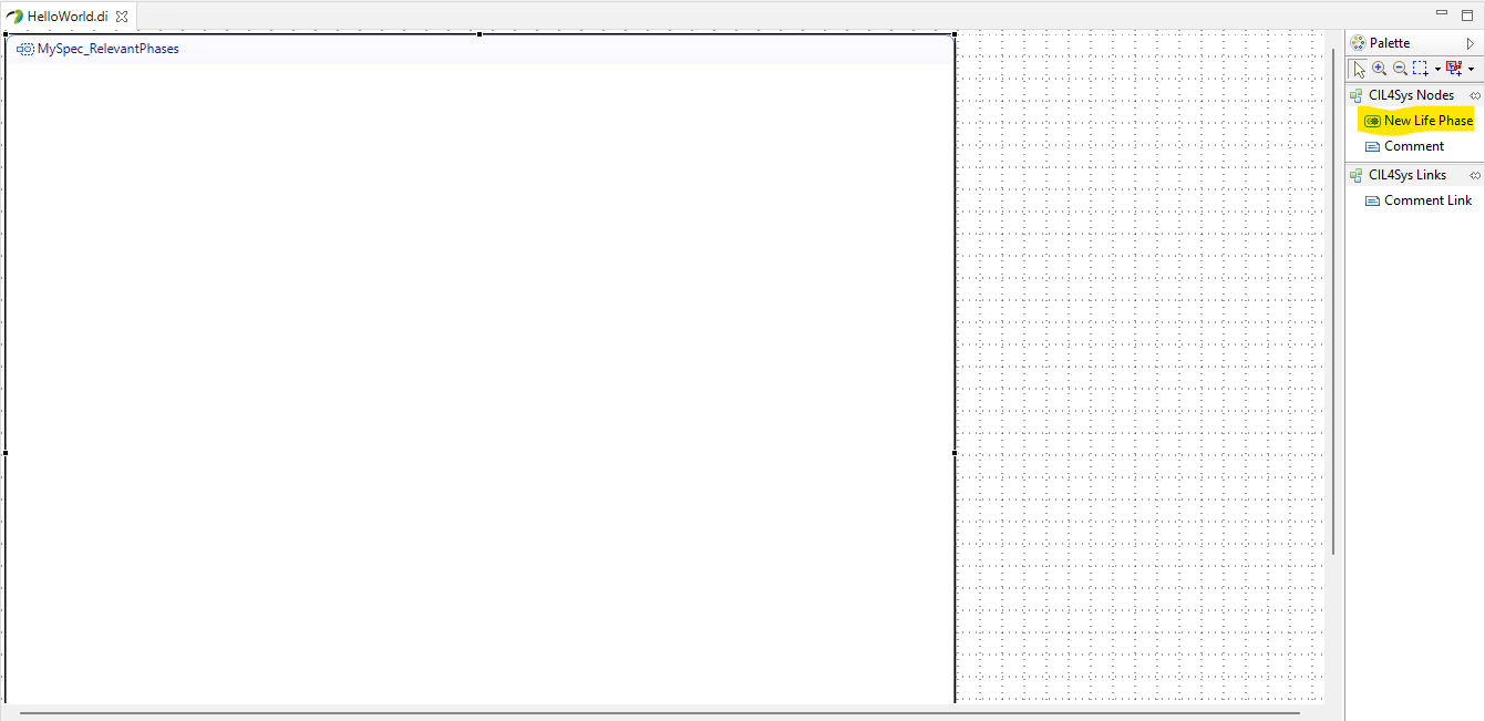
- Select Standard Use
- Click on OK

Explanation: There is no need to add a life phase to a service in Rhapsody, It will be done automaticly when completing the User Story.
Create a simple Use Case
- Papyrus
- Rhapsody
Action: Create a use case "say hello".
Explanation: The 'say hello' use case illustrates a simple yet fundamental interaction between the user and the system, where the system greets the user with a message. This use case serves as a starting point for modeling more complex interactions and demonstrates our system's responsiveness to user inputs.
- Select Standard Use
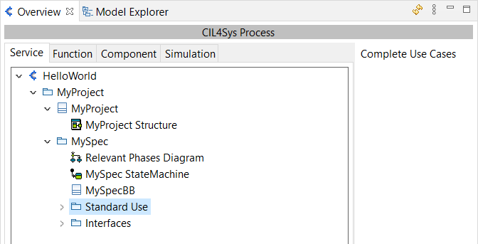
- Click on Complete Use Cases
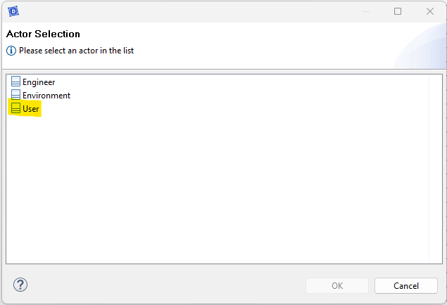
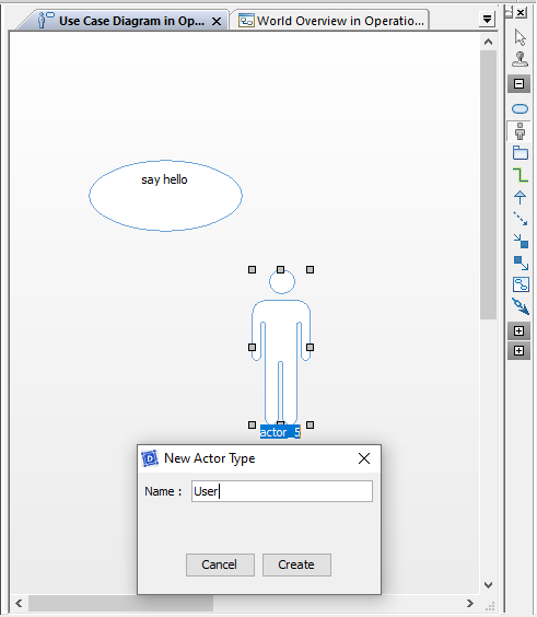
- Drag&Drop an actor on the diagram
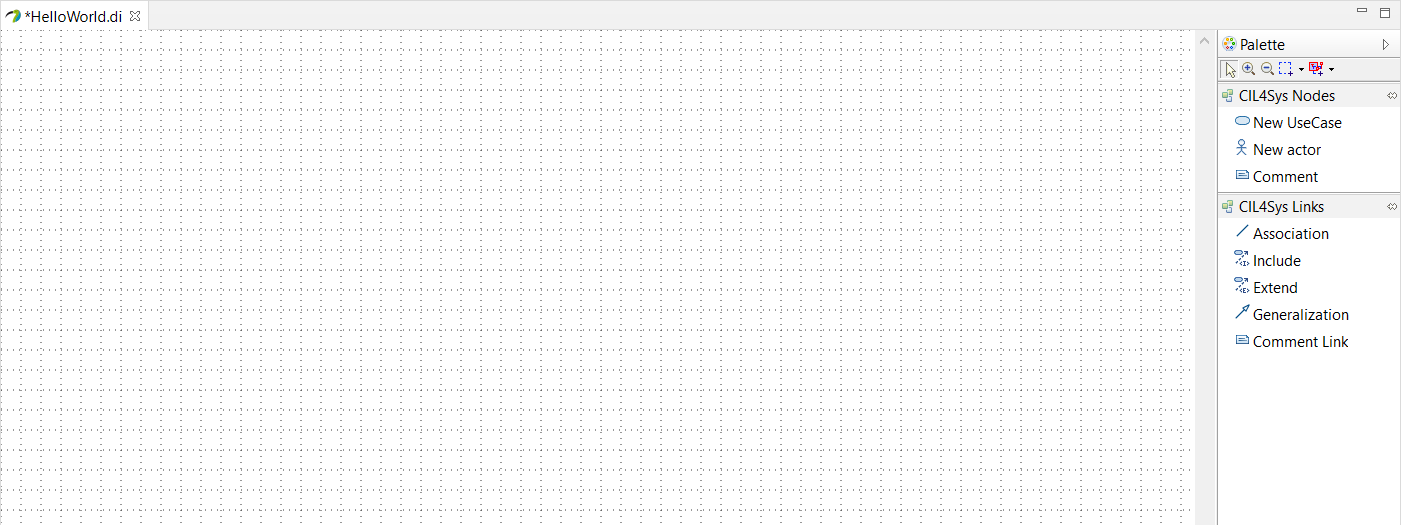
- Select User as the type of your new actor
- Drag&Drop a New UseCase on the diagram
- Type the name of the use case: say hello
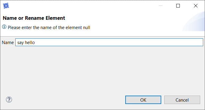
- Click on OK
- Double Click on the Use Case Diagram
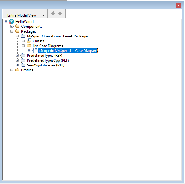
- Drag&Drop an Use Case on the diagram
- Type the name of the use case: say hello
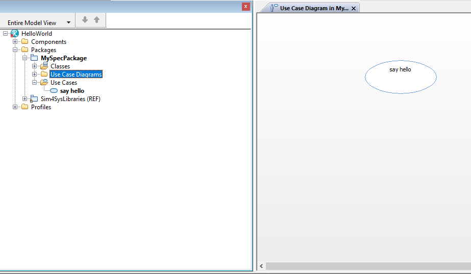
- Drag&Drop an Actor on the diagram
- Type the name of the Actor: User
- Click on Create
Create a User Story in a Use Case
- Papyrus
- Rhapsody
Action: Develop a user story within the context of a defined use case.
Explication: Crafting a user story within a use case allows you to detail specific user interactions, providing clarity on how features should behave and be experienced by the user.
- Select say hello package in the CIL4Sys Overview
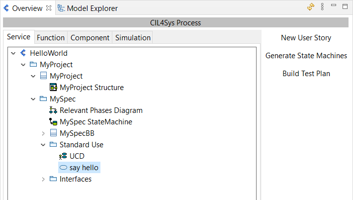
- Click on New User Story
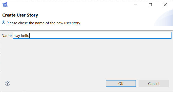
- Type the name of the user story: say hello
- Click on OK
- Double Click on the user story: say hello
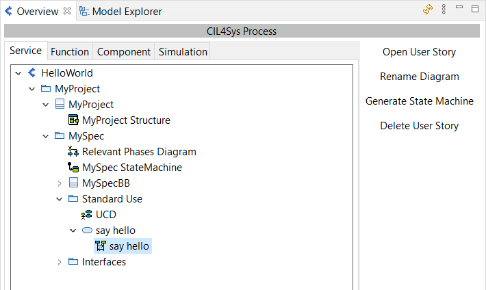
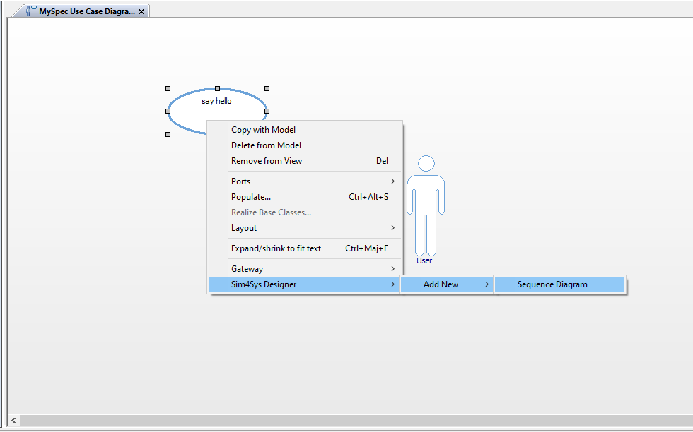
- Right Click on the use case in the diagram
- Click Sim4Sys Designer > Add New > Sequence Diagram
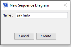
- Type the name of the Sequence Diagram: say hello
- Click on Create
Complete the User Story
- Papyrus
- Rhapsody
Action: Enrich your user story with detailed flows, states, and interfaces, and then generate a State Machine from all your user stories.
Explication: Completing the user story by adding detailed elements and generating a State Machine ensures that the dynamic behavior of the system is clearly modeled and executable, facilitating both understanding and implementation.
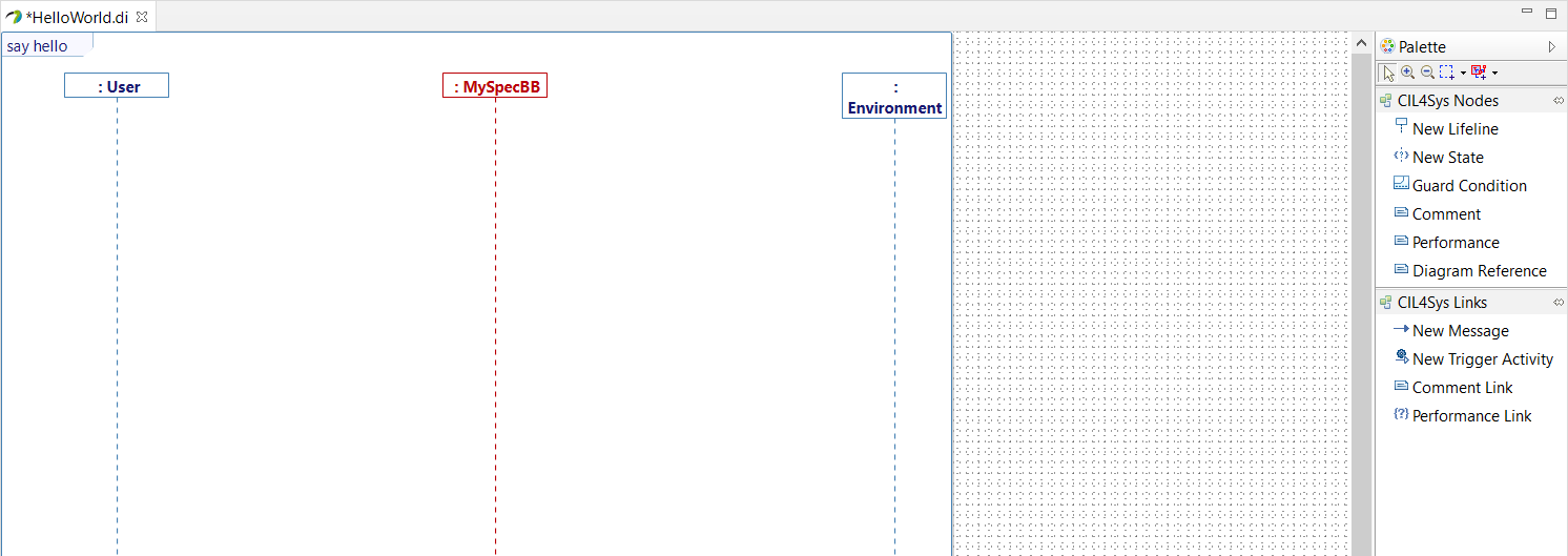
- Drag&Drop a New State on the MySpec Service lifeline
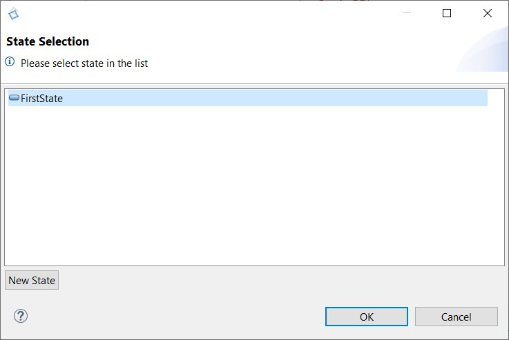
- Select FirstState
- Click on OK
- Rename the state after creation (in Active). You can do it just after the creation or by the Properties view of Papyrus
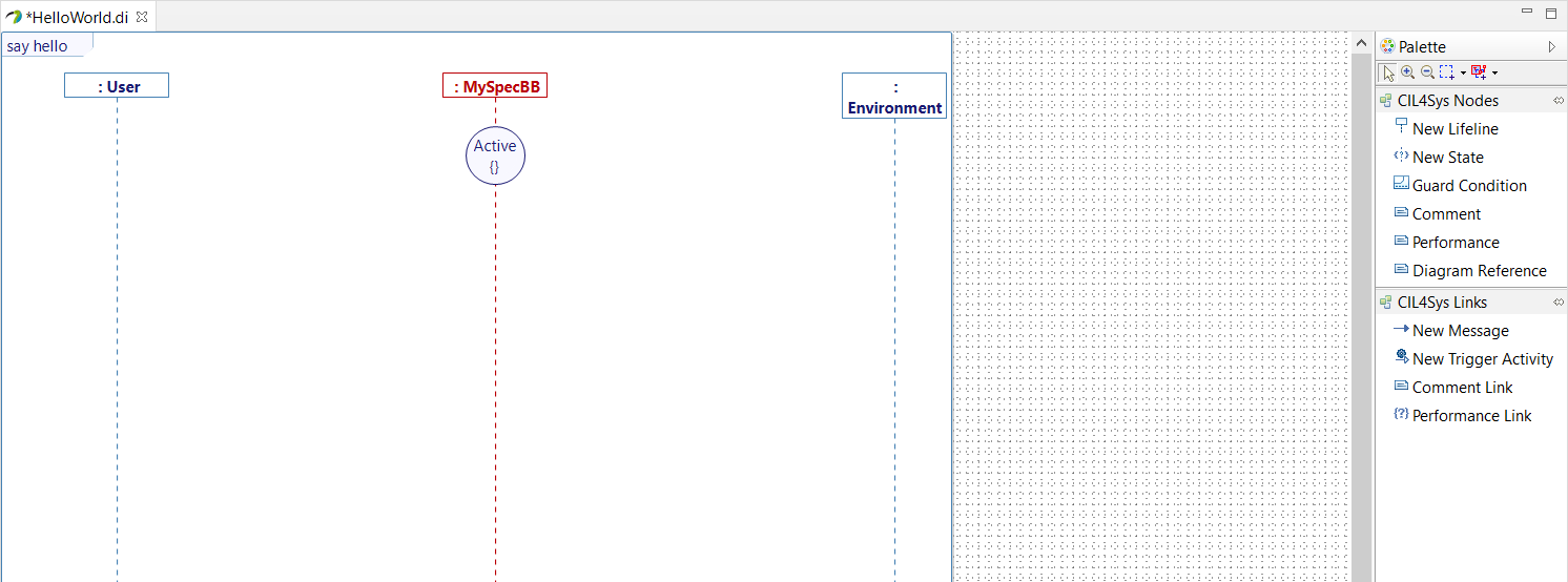
- Trace a New Message between the User lifeline and the MySpec Service lifeline
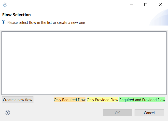
- In the Flow Selection window, click on Create a new flow

- Drag&Drop a New Interface on the diagram
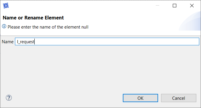
- Type the name of the interface: I_request
- Click on OK

- Drag&Drop a New Flow in the newly created interface
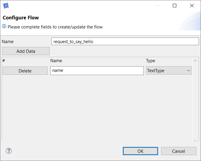
- Type the name
- Click on Add Data
- Type the name of the data: name
- Select the type of the data: TextType
- Click on OK

A good manner is to create an interface per flow.
- Go back on the user story
- Trace a New message between the user and the service
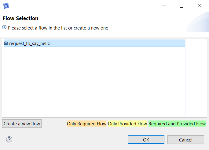
- Select the newly created flow
- Click on OK
- Trace a message between the service lifeline on itself (internal activity)
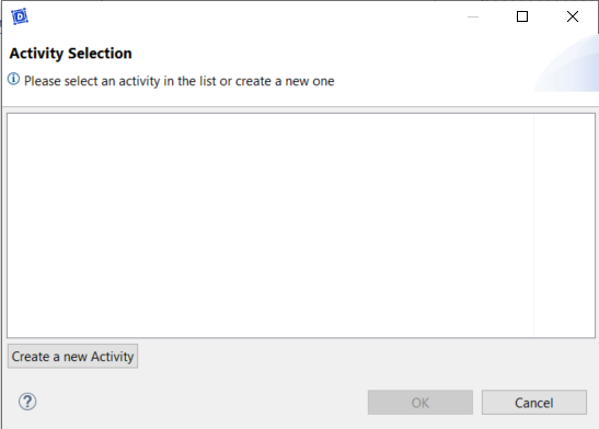
- Click on Create a new Activity
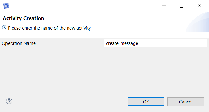
- Type the name of the activity: create_message
- Click on OK
- Right-click on the service lifeline
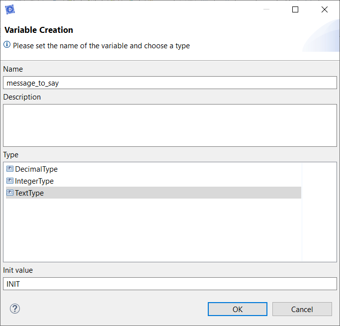
- Select Edit > Create Variable
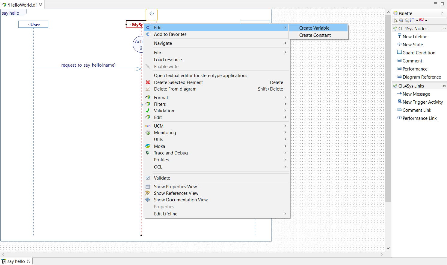
- Type the name of the variable: message_to_say
- Choose the type: TextType
- Set an init value: INIT
- Click on OK
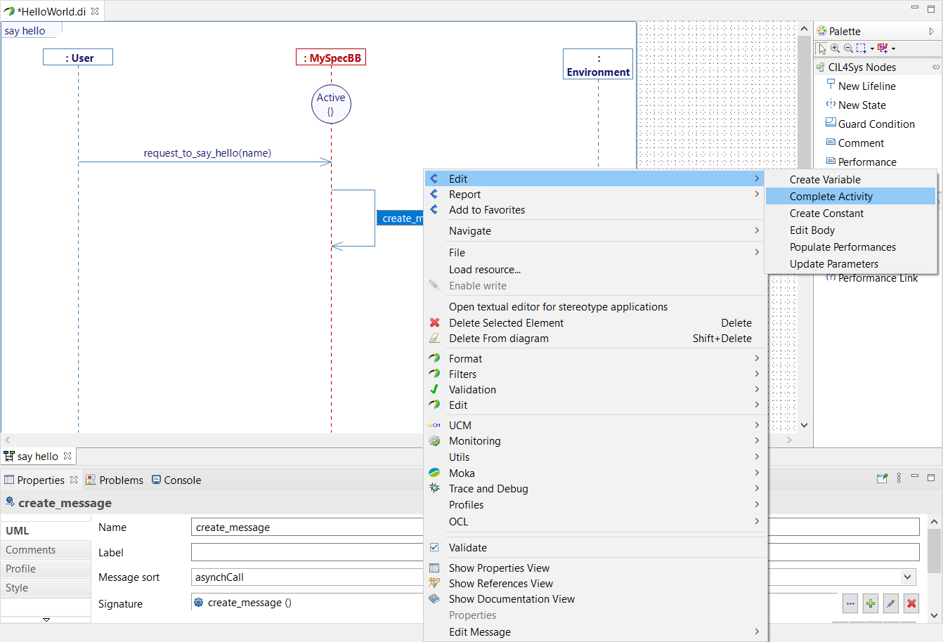
- Right-click on the create_message activity
- Choose Edit > Complete Activity
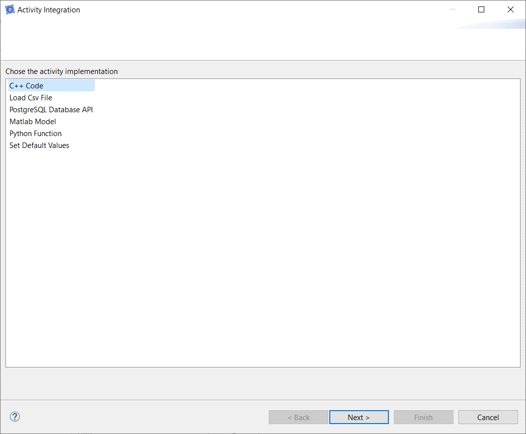
- Select C++ Code
- Click on Next
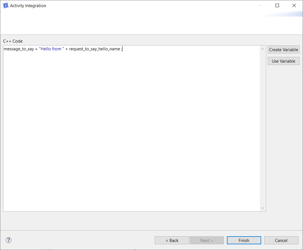
- Type the code to create_message:
message_to_say = "Hello from " + request_to_say_hello_name;
- Click on Finish
- Trace a New Message between the service and the user
- Click on Create a New Flow
- Drag&Drop a New Interface on the diagram
- Type the name of the interface: I_feedback

- Drag&Drop a New Flow in the newly created interface
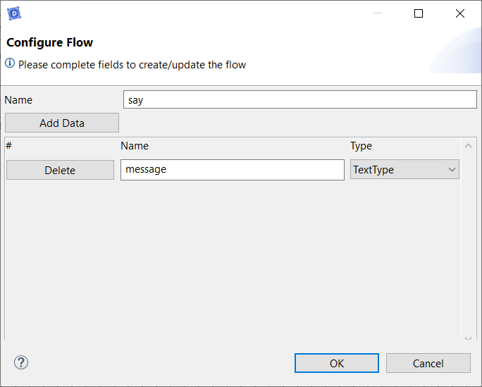
- Type the name: say
- Click on Add Data
- Type the name of the data: message
- Select the type of the data: TextType
- Click on OK

- Go back on the user story
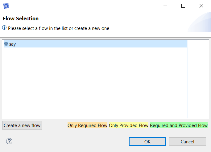
- Trace a new message between the service and the user
- Select the newly created flow
- Click on OK
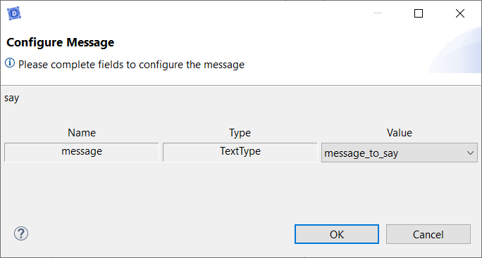
- Select the data value: message_to_say
- Click on OK

- Select the user story in the CIL4Sys Overview
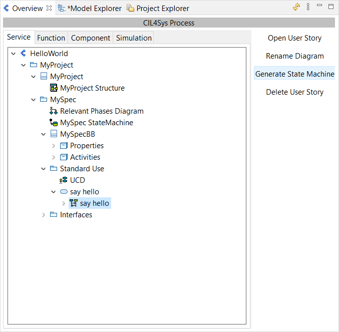
- Click on Generate State Machine
- Click on Ok in the confirmation dialog box
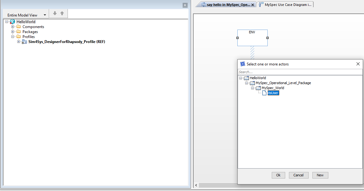
- Drag&Drop a System Border on the Diagram
- Select itsUser
- Click on Ok
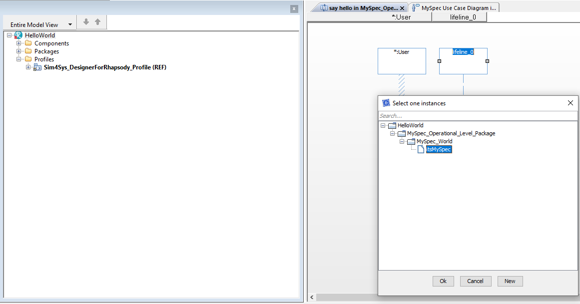
- Drag&Drop a Lifeline on the Diagram
- Select itsMySpec
- Click on Ok
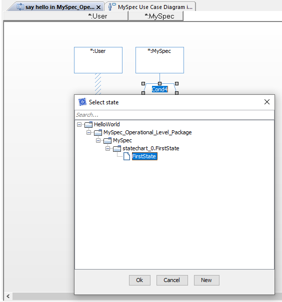
- Drag&Drop a Entrying State Condition Mark on the MySpec lifeline
- Select FirstState
- Click on OK
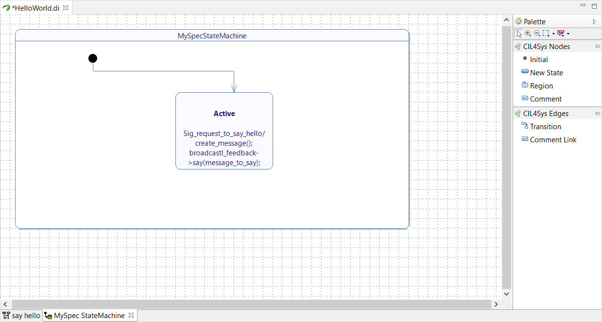
- Rename the state after creation (in Active). You can do it just after the creation or by the Properties view of Rhapsody
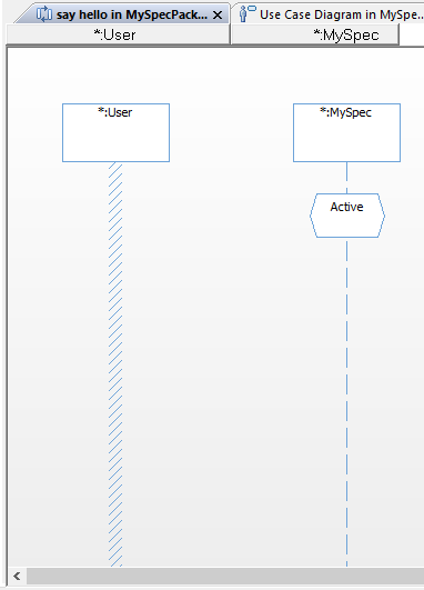
- Trace a New Message between the User lifeline and the MySpec lifeline
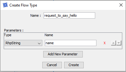
- Click on New
- Type the name of the Flow: request_to_say_hello
- Add New Parameter with type Rhpstring and Name name.
- Click on Create
- Click on Connect
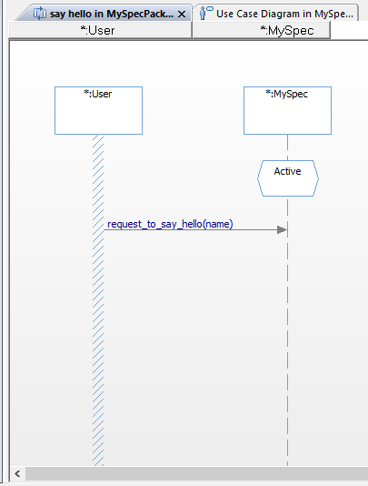
If the name is not change after the popup press escape
- Trace a message between the MySpec lifeline on itself (internal activity)
- Click on New
- Type the name of the activity: create_message
- Click on Create
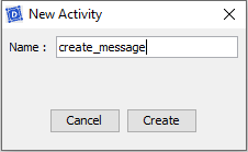
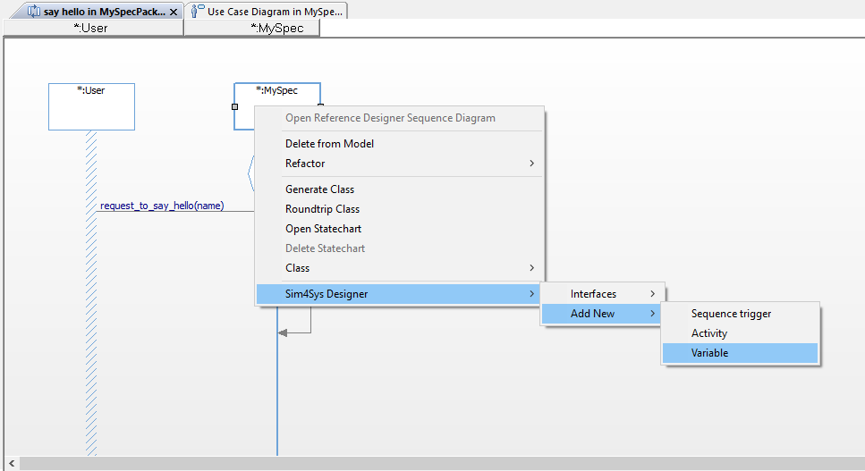
- Right-click on the MySpec lifeline
- Click on Sim4Sys Designer > Add New > Variable
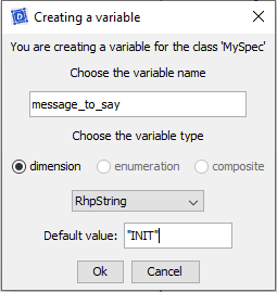
- Type the name of the attribute: message_to_say
- Choose the type: RhpString
- Set an init value: "INIT"
- Click on OK
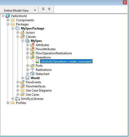
- Double Click on the create_message operation under MySpec
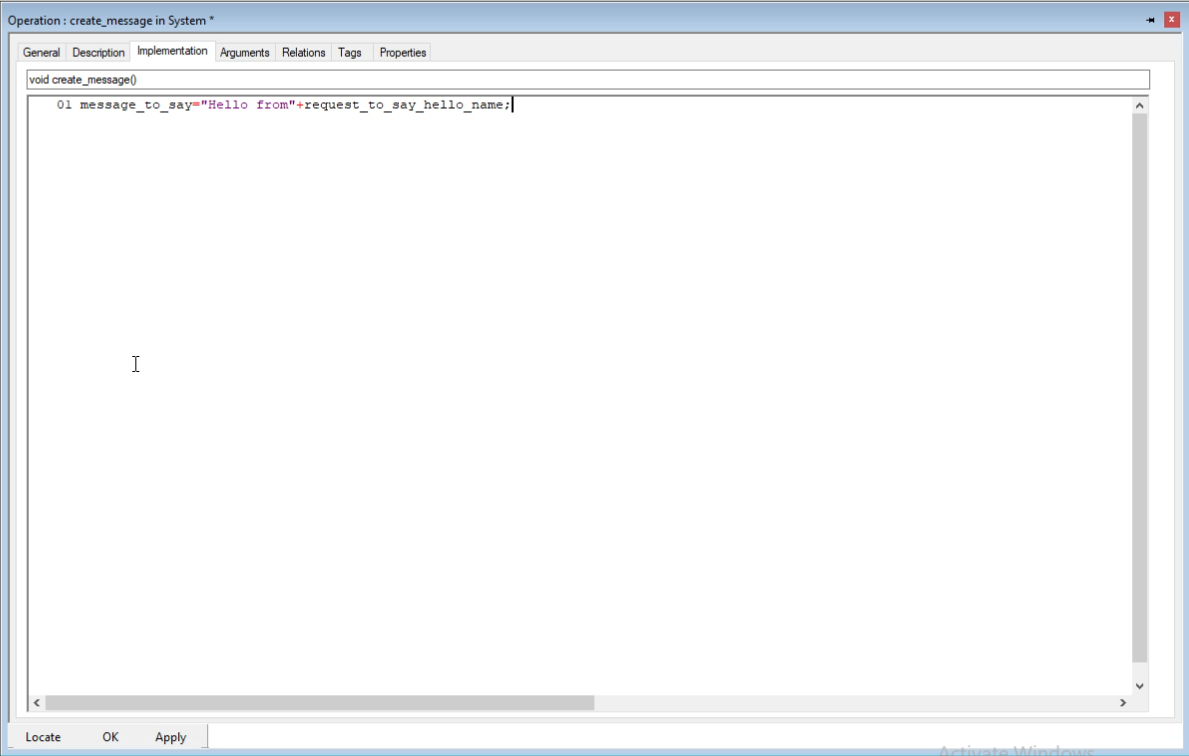
- Click on Implementation
- Type the code to create_message:
message_to_say = "Hello from " + request_to_say_hello_name;
- Click on OK
- Trace a New Message between the lifeline MySpec and the user
- Click on New
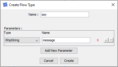
- Type the name of the Flow: say
- Add New Parameter with type RhpString and Name message.
- Click on Create
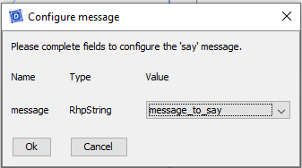
- Click on Connect
- Select the data value: message_to_say
- Click on OK
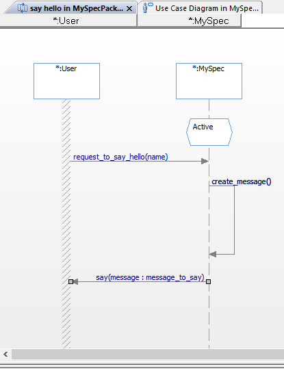
- Right Click on the Sequence Diagram
- Click on Sim4Sys Designer > Statecharts > Generate transitions
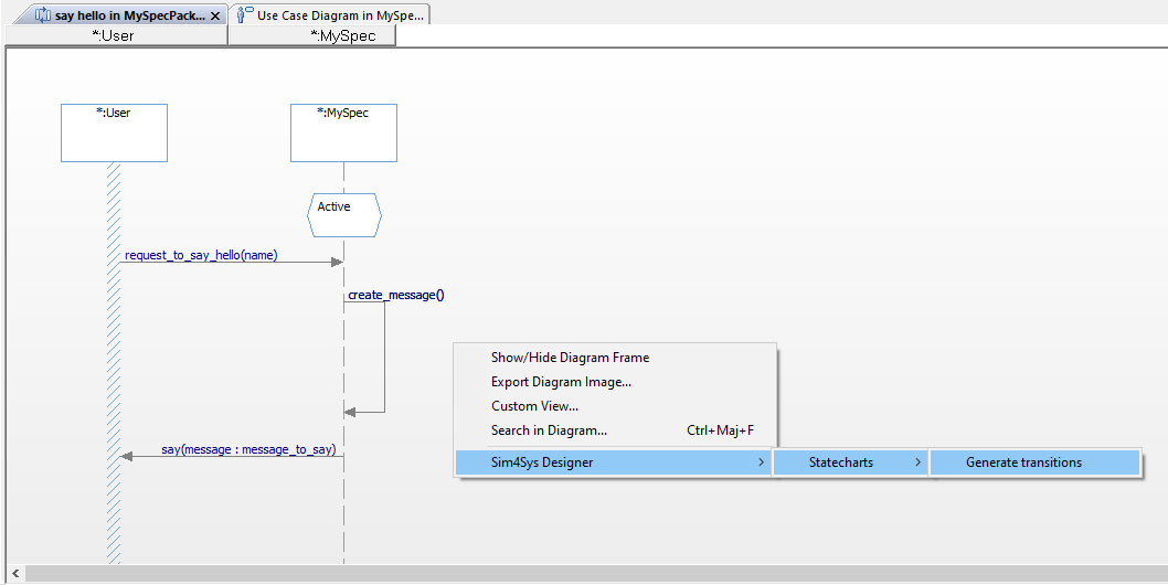
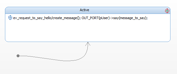
Generate Code
- Papyrus
- Rhapsody
Action: Convert your detailed state machine into executable C++ code.
Explication: Generating C++ code from your state machine directly translates your model’s dynamics into a programmable format, bridging the gap between design and practical application.
If you have the community version of Designer (free version), please build the executable via Hub4Sys as shown on this page
- Before generating the code, ensure that the CIL4SysLibs are already part of the project.

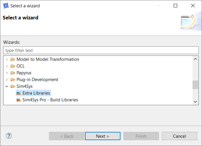
- If it's not the case, you must add the Libs in File > New > Other... In the new window, select Extra Libraries in the Sim4Sys folder. If you have a Pro access, you can add Sim4Sys Pro - Build Libraries instead:

- Click on the Overview menu, thanks to the following icon:
![[Code] Generate and build [Code] Generate and build](/img/tutorials0/40_Generate_and_build.png)
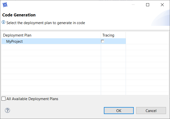
- Click on [Code] Generate and build in CIL4Sys Overview
- Select MyProject
- Click on OK
- Select Cygwin GCC
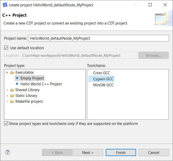
- Click on Finish
- Click on OK in the confirmation dialog box
You can also compile with MinGW.
To do that, please follow this process.
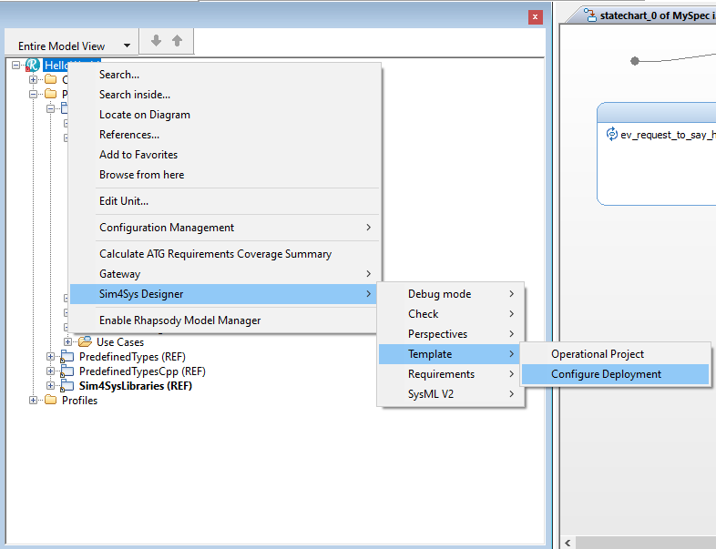
- Right Click on the Project
- Click on Sim4Sys Designer > Template > Configure Deployment
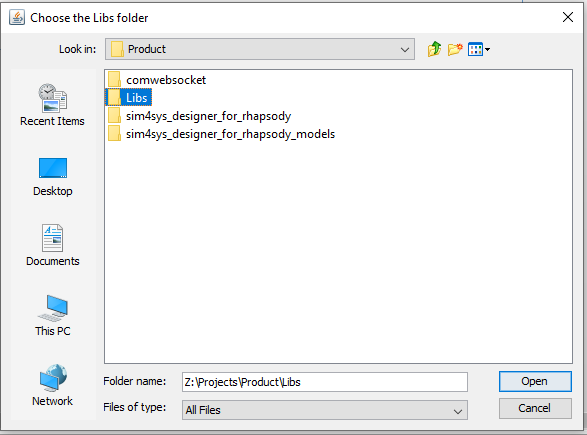
- Choose the folder called : Libs
- Click on Open
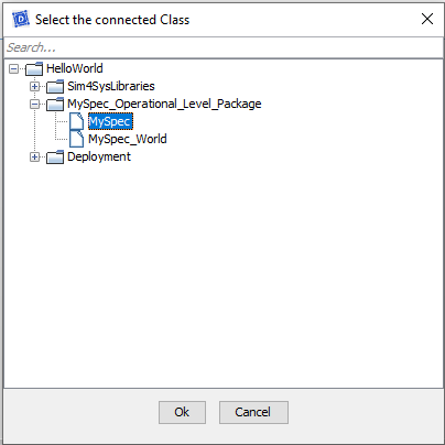
- Choose the System MySpec to connect it to Virtual Bench.
- Click on OK
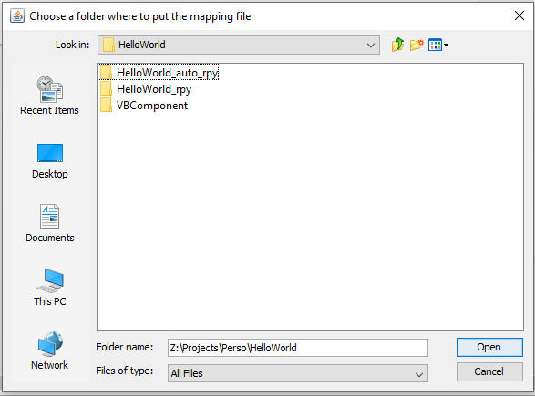
- Choose the folder where you want to put the .xml file.
- Click on Open
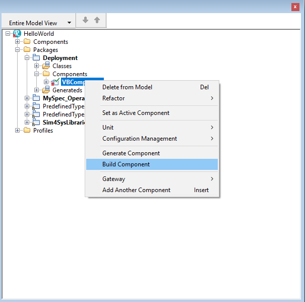
- Open the Components in the Deployement package.
- Right Click on VBComponent
- Click on Build Component
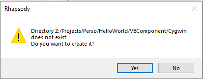
- Click on Yes
Export a XML
- Papyrus
- Rhapsody
Action: Export the model to an XML file for integration with Virtual Bench.
Explanation: Exporting our model to XML plays a crucial role in preparing for simulation. This allows us to seamlessly transfer the model's structure and data to Virtual Bench, where we can simulate and test the system's behavior in a controlled environment. This step ensures that our design meets expectations before going into production.
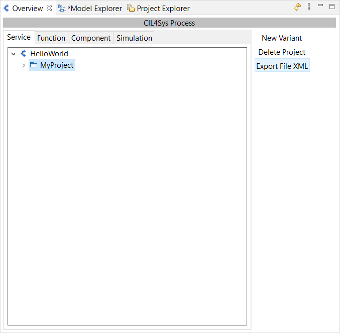
To do so, in Overview, Service Tab, select your project and click on Export File XML.
Explanation: There is no need to export the XML file, It was done automaticly when generating the code.
VISUALIZATION WITH VIRTUAL BENCH
The grand finale involves exporting your meticulously crafted model into XML and bringing it to life with a visualization. This step underscores the utility of models beyond their native environment, showcasing interoperability and the seamless flow from model to visualization.
This part focus on how to set up communication between the model and the visualization.
Login on VB
Log into the Sim4Sys Virtual Bench platform to start setting up your model for the visualization.
-
Go on the Sim4Sys Virtual Bench: https://sim4sys.com/
-
Identify with your login and password
-
In the Projects tab choose your sandbox project

If you don't have a sandbox, you can create one by clicking on New Project. Then, in the Project name field, you can write "Sandbox your name" and in the Project URL field, "sandbox".
Add Executable & Import Types and Flows
Action: Incorporate the executable in Virtual Bench and import the types and flows from your model.
Explication: Adding the executable and importing model data into Virtual Bench prepares the visualization environment, enabling you to test and validate the system's behavior under visualized conditions.
-
In the Project tab, open the Executables folder, in which you can add a new executable:

-
You can name it as you want, choose the path to the executable, otherwise, click the red cross to remove the path, then press Save:

-
A pop-up opens to ask if you want to import types and flows from the model to the virtual bench:

-
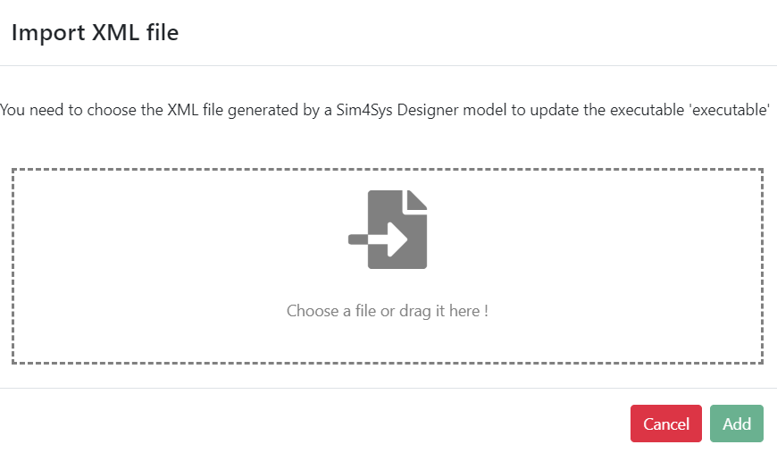
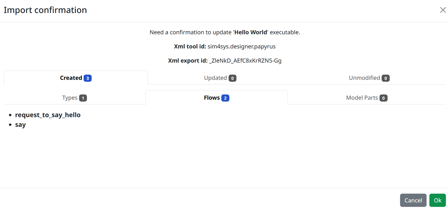
If you click on Ok, the below pop-up ask you to add the .xml file:
- Then, check that the types and flows are correct and click on Ok
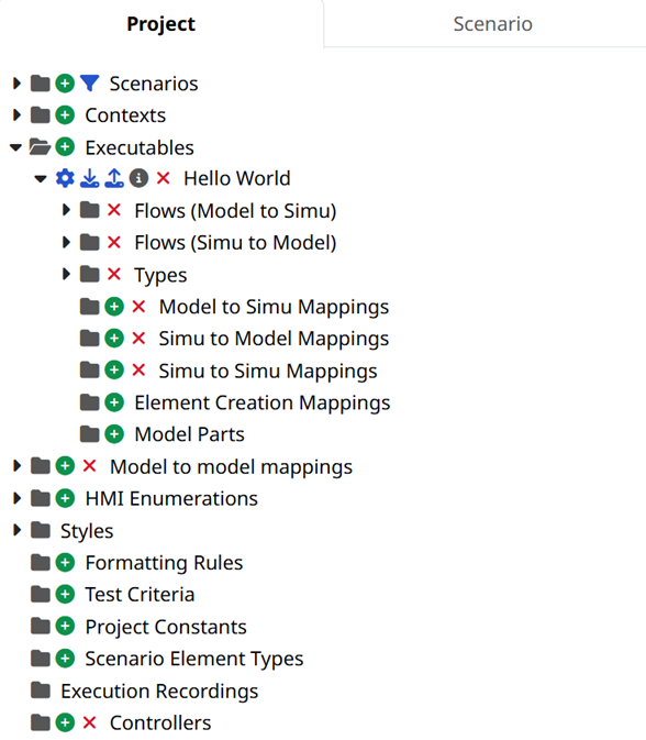
- Back in the Executable folder, expand your new executable. For this, you can click on the small black arrow on the left side of the folder, or you can directly double-click on the folder itself.
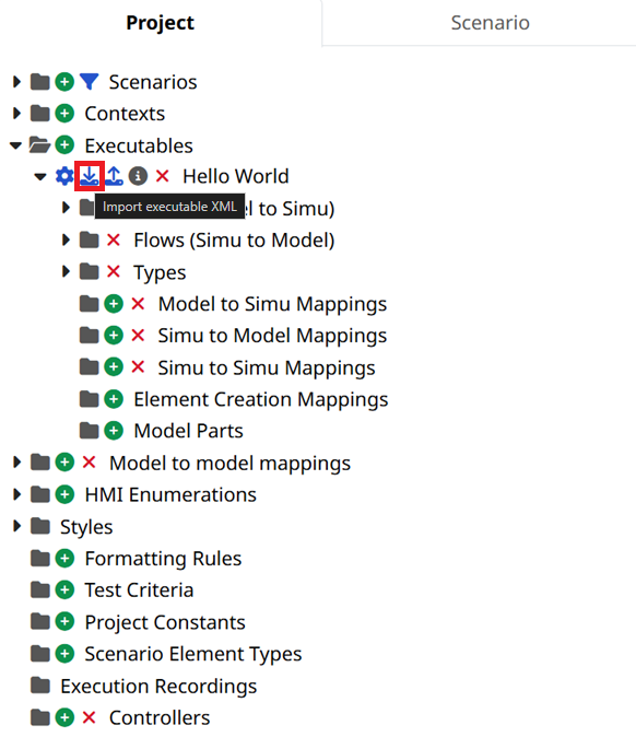
- If you updated the .xml file, just click on Import types and flows close to the executable name to reload it:
- In the Import XML file window, select the XML file you generated earlier (it is located into HelloWorld\export folder)

Simu to model mapping is the part where we manage how the visualization will interact with the model that we've created with Papyrus.
Context
Action: Add HMI, Scene2D, and Timeline contexts in Virtual Bench for visualization.
Explanation: Contexts such as HMI, Scene2D, and Timeline enhance our visualization environment, providing visual and temporal frameworks to observe the system's behavior. Each context offers a unique perspective on the visualization, from the user interface to spatial representation and the timeline of events, increasing our understanding of the system as a whole.
- Add Scenario contexts by clicking on the
 sign.
sign.
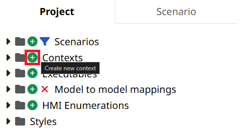
- For this tutorial, we will need 3 contexts: HMI, Scene2D and Timeline (see here for more information).
Add a New Scenario
Action: Set up and add a new scenario in Virtual Bench, dictating the sequence of events that your model will undergo in the visualization.
Explanation: Creating distinct scenarios enables the simulation of different interactions and behaviors of the system under varied conditions. This helps to test the system's robustness and to identify potential pitfalls before actual implementation, ensuring that the system is well-suited to its future usage environments.
- Once you created your contexts, add a new scenario

- Name it as you wish, and press Ok. The new scenario should now be opened if you selected Open the new scenario option.
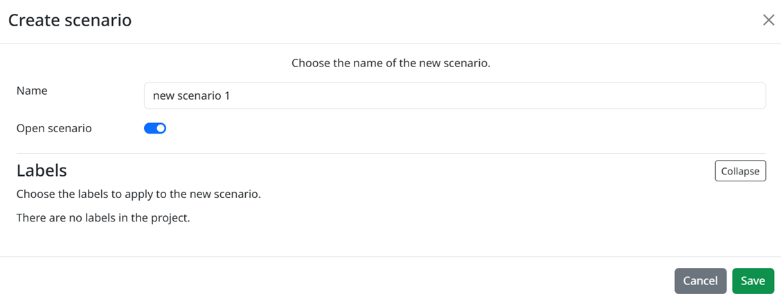
To open a scenario you can double click on the scenario's name or click on the eye next to the scenario's name.
Before creating new mappings, in your scenario tab, Add a new WebSockets, related to the Executable that you added earlier.
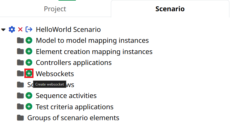
Mapping
Action: Establish mappings between the types and flows defined in the model and their representation in Virtual Bench.
Explanation: The mapping process is essential for aligning the elements of our model with the components of the simulation. This ensures that data flows correctly between the model and the simulation, allowing for accurate analysis of system-user interactions and the detection of any anomalies or opportunities for improvement.
Mapping of request_to_say_hello
Now let’s map the flow request_to_say_hello. To do that, see the following steps:
- Add a Simu to model mapping element by clicking the + sign.
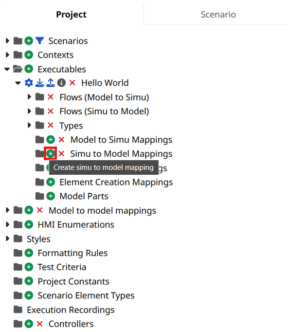
What we want to do is to create a Timeline action, that is, an element that maintain one action over a certain period of time (for more details, please refer its page). Here we will use this to trigger request_to_say_hello.
- Select the Timeline action element to interact with the model. And choose the request_to_say_hello flow.

- Select the value parameter to be transmitted when the Timeline action will be started.

We need to create the element that will be linked to this mapping.
- Switch to Edit Mode if you are in Run Mode, by clicking on the button:

- In Edit mode, in the context menu below, select the timeline context (don't forget to add a timeline context before that).

The timeline context is where you can visualize your story through the time. For now, the Timeline events line is the only timeline that we need to focus our attention on.
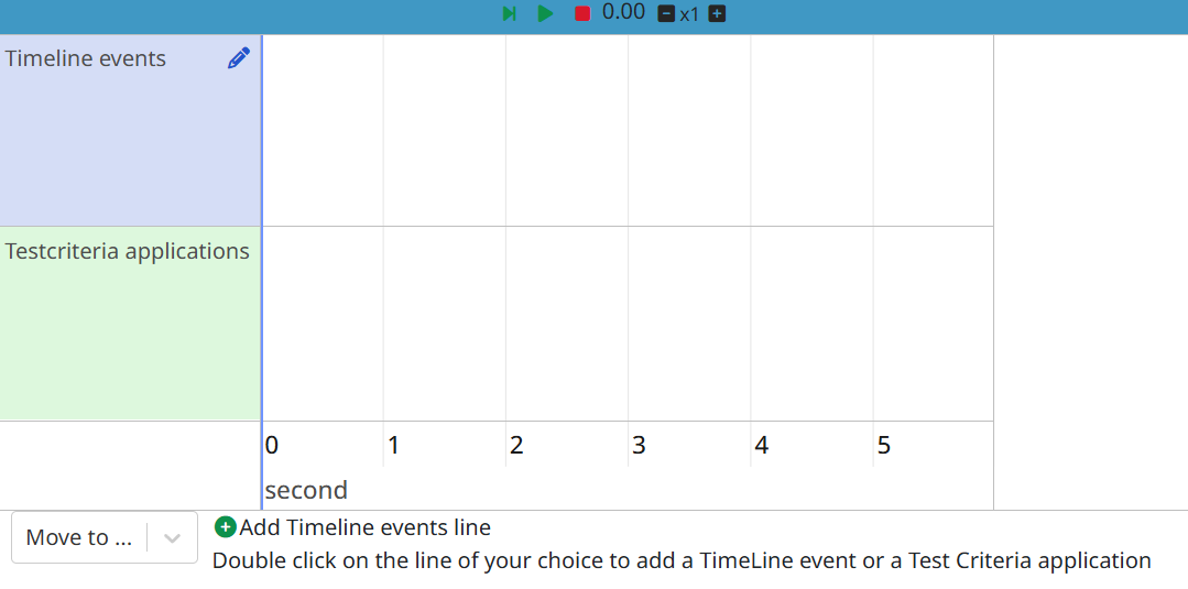
You can add an element by double clicking on the timeline events axis. If you ever want to move an element, you can select it, then drag it with your mouse, by pressing the Alt key on your keyboard.
You can also zoom/dezoom the time axis scale by scrolling with the mouse wheel.
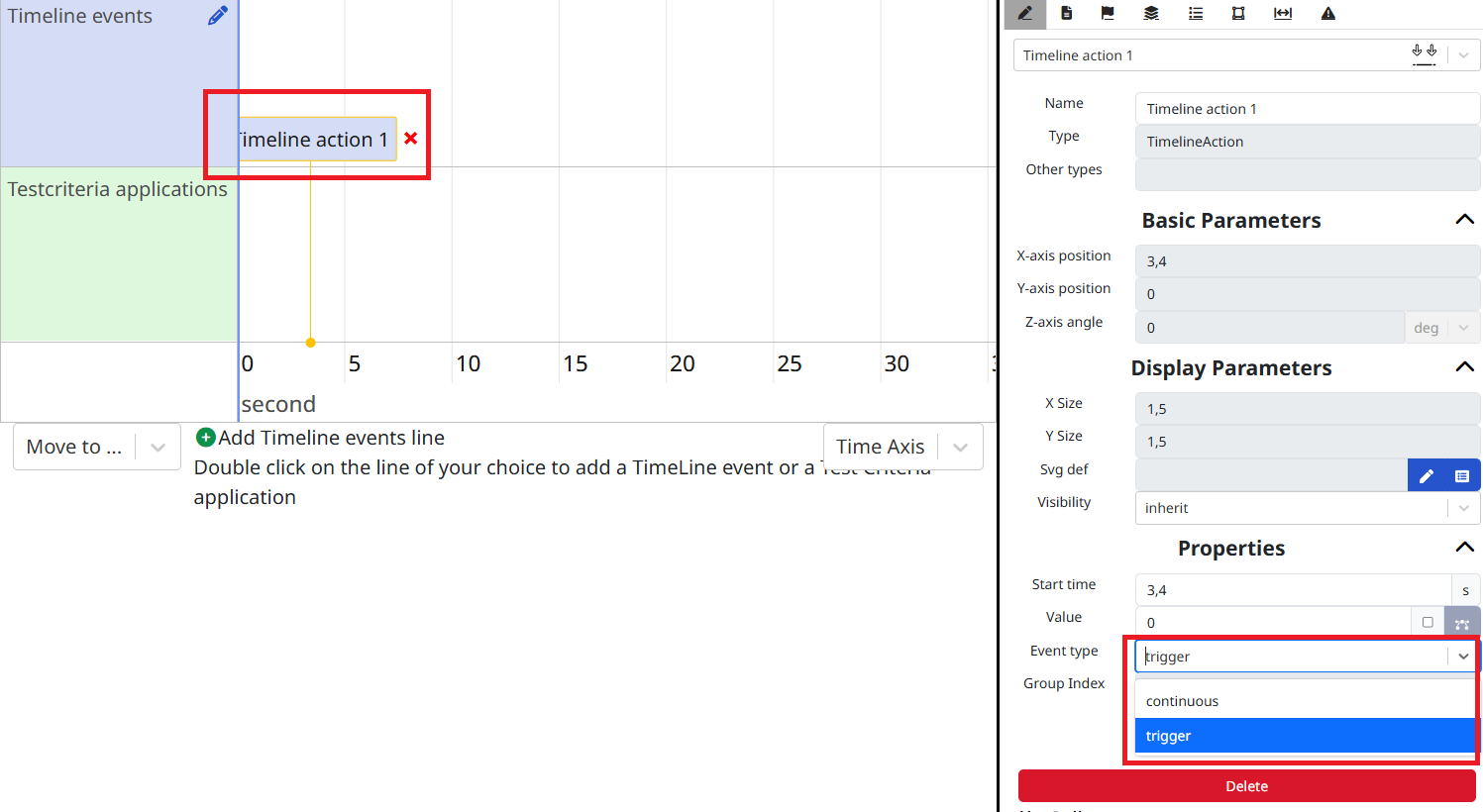
- Double-click somewhere in the timeline events axis to add a timeline action element. Then select it, and go to the Parameter tab and change the Event type from "continuous" to "trigger" (in order to send the associatied mapping only one time), and click on Save on the TimelineAction popup to save the modifications
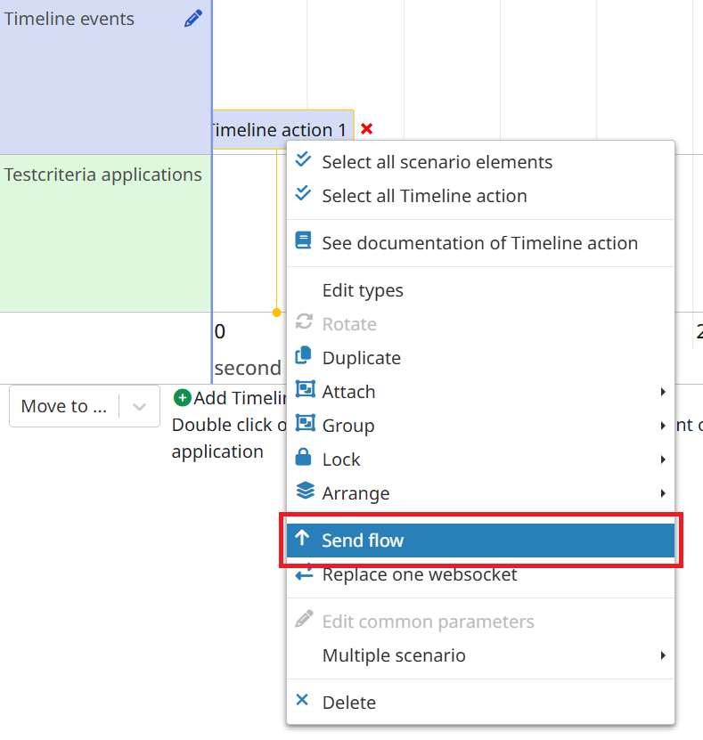
- Right-click on the action and select Send flow.
- Virtual Bench will ask you if you want to Create a new mapping, or Reuse an existing one, select Reuse:

- Select the correct items and click on Save.

Mapping of say
We need to create the simu to model mapping for the speed flow sent to the model (say).
We will see another way to create and add a mapping at the same time:
- In the context menu below, select the HMI context.

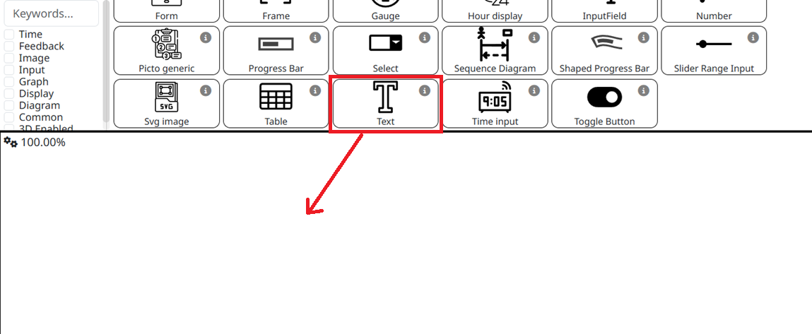
- In this menu, to the right, Drag&Drop the Text element:
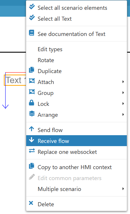
- Right-click on the Text element and select Receive flow:
-
Virtual Bench will ask you once again if you want to Create or Reuse a mapping, select Create this time.
-
Select the flow say:

- Select the Text parameter to be the data modified by the flow, switch from "constant" to "variable" and click on the Variable Selection button
 to be able to select the parameter message from the flow say.
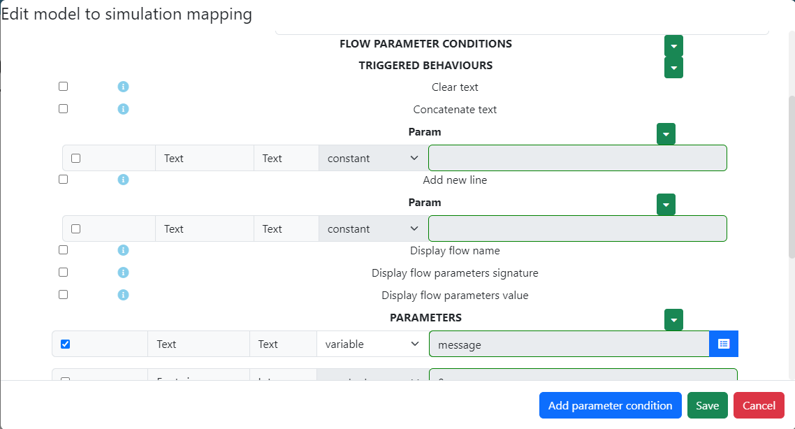
- Click on Ok then Save.
Run scenario
Action: Run the configured simulation scenario and analyze the results to evaluate the system's performance.
Explanation: Executing the simulation gives us a direct window into how our system operates in a controlled environment. By analyzing the results, we can identify the strengths and weaknesses of our design, adjust parameters to optimize performance, and validate that the system meets the needs identified in the initial modeling stages.
Now, it's time to run your scenario and see your Hello message.
-
Next to the executable you have created, click on the cog
 . A pop-up window will appear, type the path of the executable you have generated with Designer. The executable should be in the Debug file of the DefaultNode folder.
 -
Switch to Run Mode by clicking on the pencil button
 located on the top left of the page.
 -
Start the Launcher
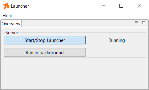
- While your Designer project is running, connect the WebSocket by clicking on Launcher connection button located on the top-right. It will switch from the red color to the green color (as same as websocket button):

If you don't see the websocket button please change the preference.
When running the executable for the first time, windows might try to prevent it from being executed. In order for it to run now and for each future executions, when the following popup appears, click on "More info", then click on the "Run anyway" button.
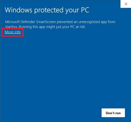
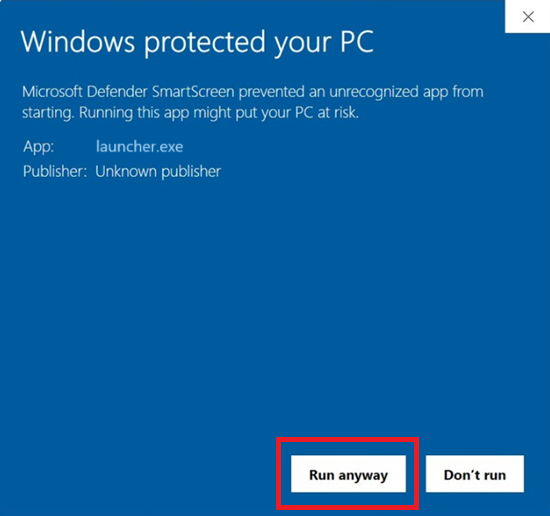
You can open the contexts HMI and Timeline. Each context will be opened in a dedicated window.
In order to save your time, we have set up a backup system for the positioning of your secondary windows, taking into account the dimensions of each window, their positions on your screen and their zoom levels.
To save windows configuration you must click on the button which is in navigation bar: 
-
Click on the Play ► button. It will bring all the opened contexts windows in the foreground automatically.
-
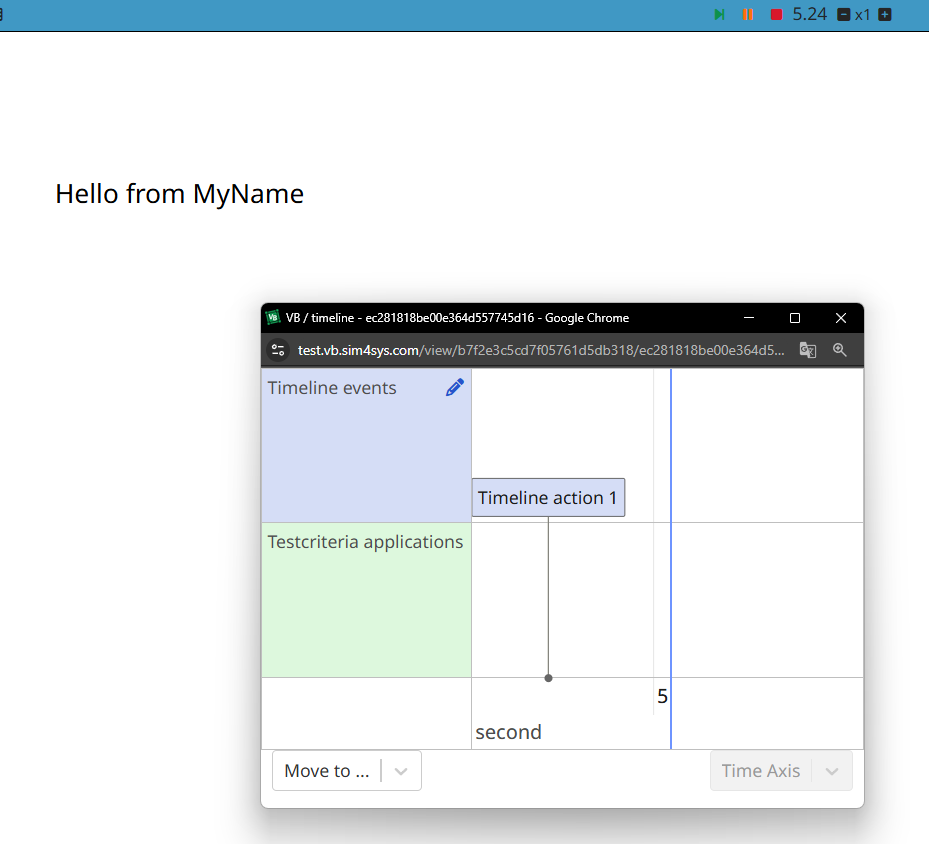
Follow the timeline, and check if your Hello message appears.
Next Steps: Refinement Based on Visualization Feedback
Continuously refine your model based on insights gathered from visualization feedback to ensure that the system remains effective and adapts to new challenges. This approach of using data and insights to enhance the model increases its long-term value and relevance, ensuring that it effectively meets evolving requirements and challenges.