Start to use Sim4Sys with a simple model (blackbox)
PRESENTATION
This tutorial is an introduction to the practice of the method. You will be guided through the process to realize your first model and the associated simulation.
Prerequisites
You should have already done the first tutorial Hello World.
News skills that you will acquire
On Designer:
- Define a Type,
- Add conditions in a User Story.
On Virtual Bench:
- Edit a Context,
- Use new Context elements: Gauge, Car, Road Pavement,
- Add a Curve Profil.
Duration
2h
CREATE A MODEL
- Click on File > New > Papyrus Project

- Select CIL4SysLanguage checkbox
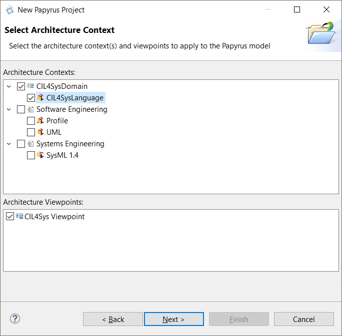
- Click on Next
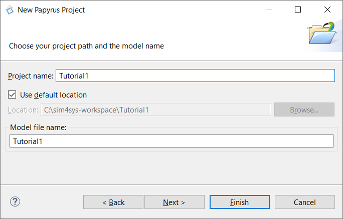
- Type the name of the Papyrus Project: Tutorial1, in the project name field
- Click on Next
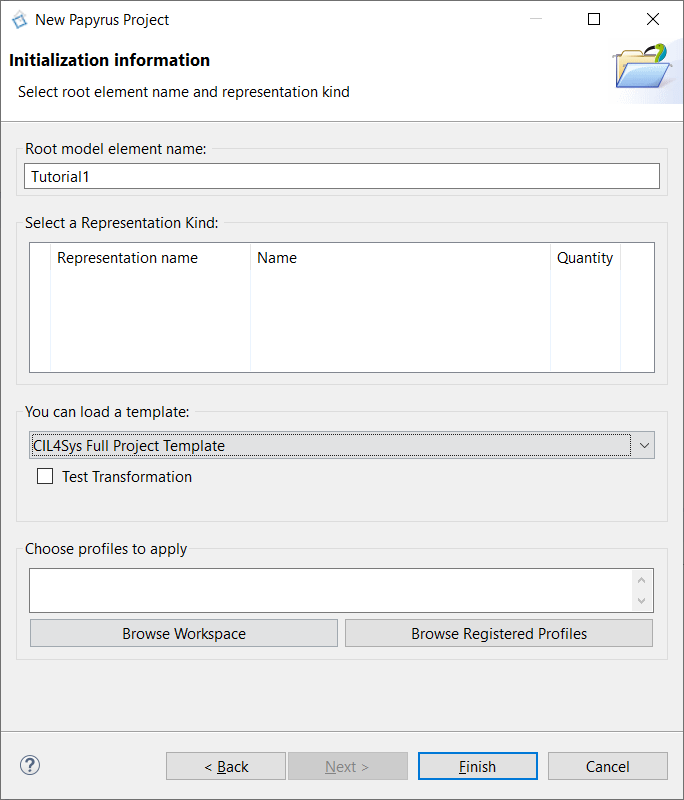
- Select CIL4Sys Full Project Template in the field: “You can load a template”
- Click on Finish
CREATE A PROJECT
- Select Tutorial1 in CIL4Sys Overview. You can use the Refresh View button when selecting the Overview tab.

- Click on New Project

Sometimes, the button does not appear because of the size of the window. You can either resize the Overview tab horizontally or use a bigger screen.
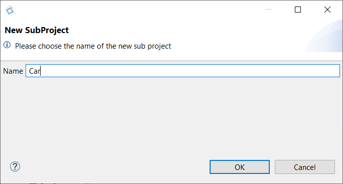
- Type the name of the project: Car
- Click on OK
- Click on Ok in the confirmation dialog box
CREATE A SERVICE SPEED MANAGEMENT
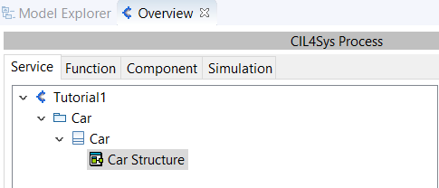
- Double Click on the Car Structure diagram
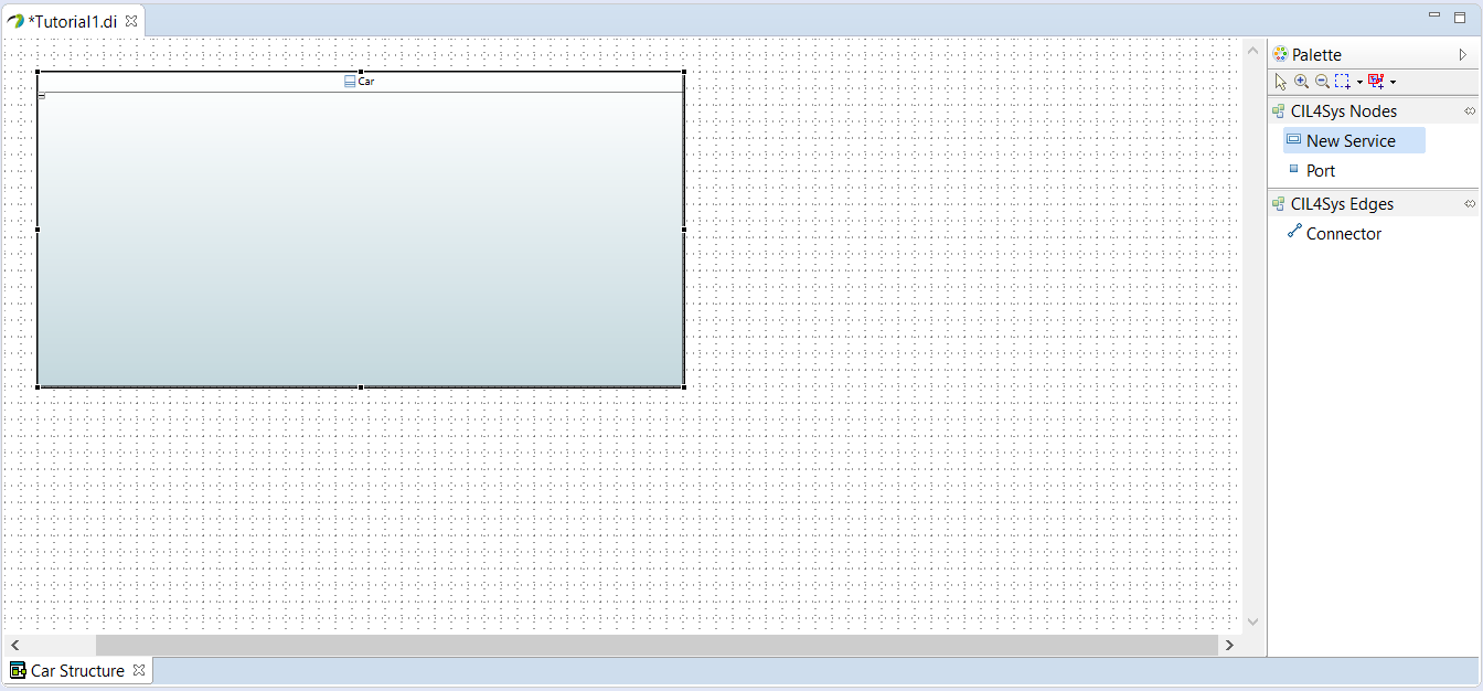
You can resize the composite structure diagram by dragging the corners
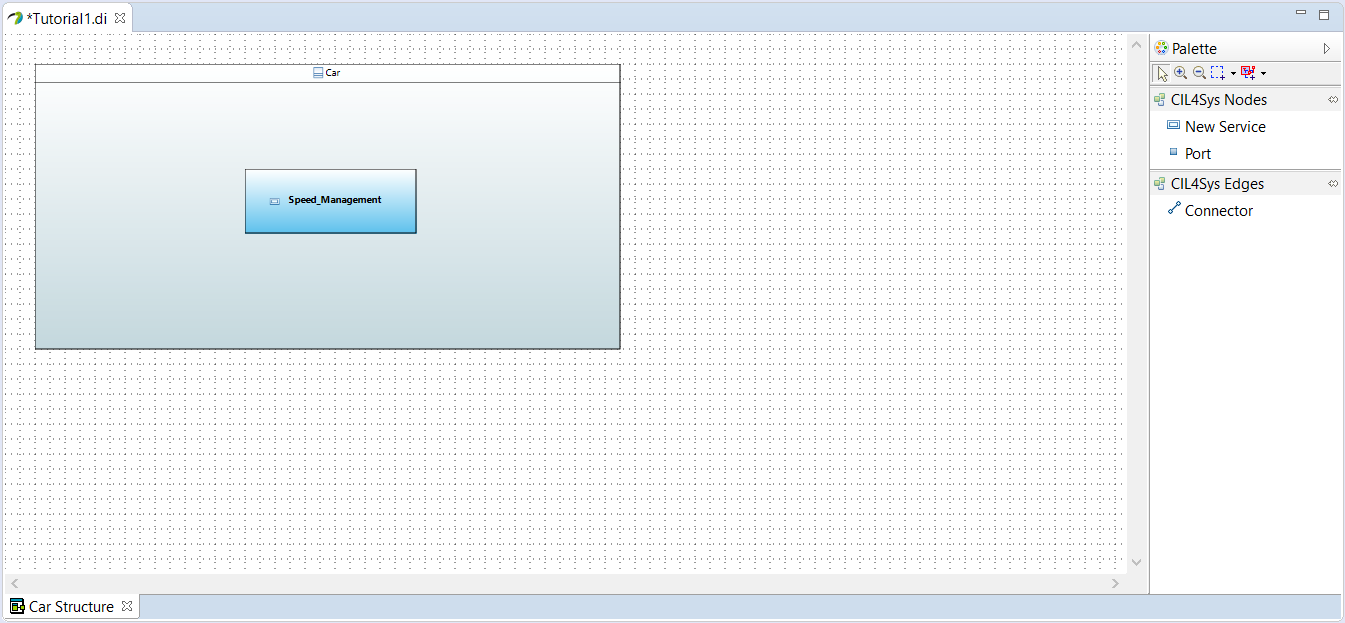
- Drag&Drop a New Service in Product CSD
- Select Create
- Type the name of the service: Speed_Management
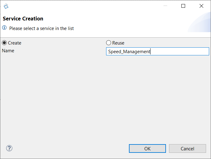
- Click on OK
ADD A LIFE PHASE TO A SERVICE
- Select Speed_Management Package in CIL4Sys Overview (refresh if it does not appear).
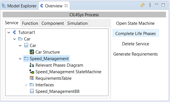
- Click on Complete Life Phases
- Drag&Drop a New Life Phase in the diagram for relevant phases of the service
- Select Standard Use
- Click on OK

CREATE A SIMPLE USE CASE
- Select Standard Use
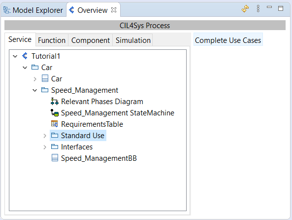
- Click on Complete Use Cases
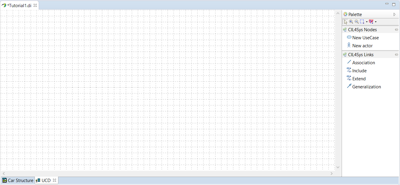
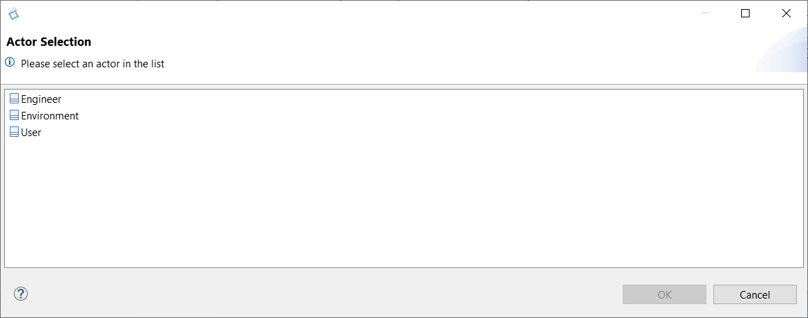
- Drag&Drop an actor on the diagram
- Select User
- Click on OK
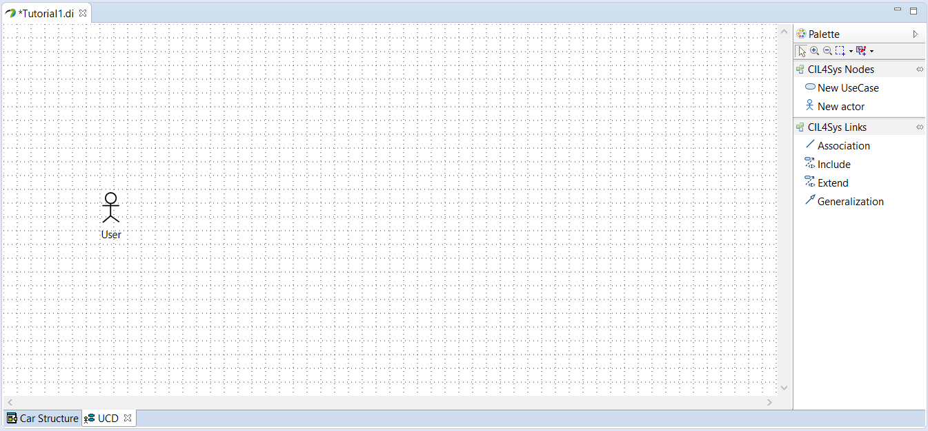
- Drag&Drop a New UseCase on the diagram
- Type the name of the use case: Accelerate
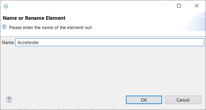
- Click on OK
- Trace an association between the actor and the use case
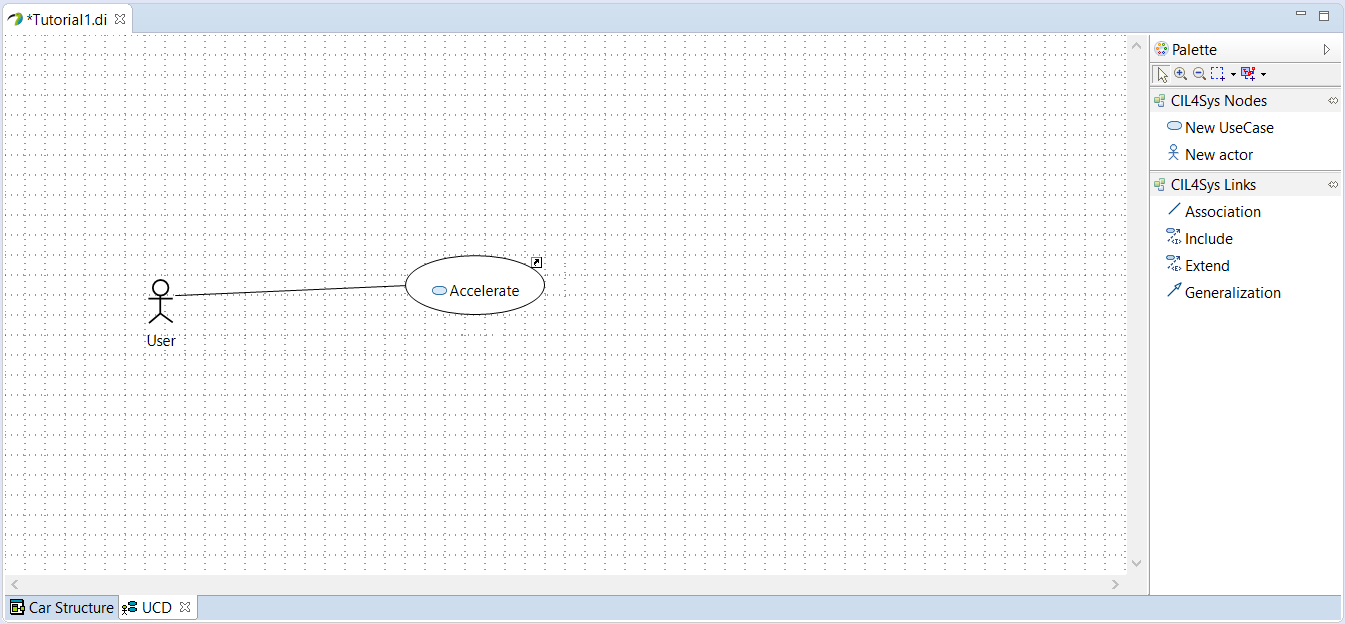
CREATE A USER STORY IN A USE CASE
- Select Accelerate package in the CIL4Sys Overview
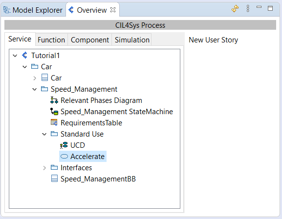
- Click on New User Story
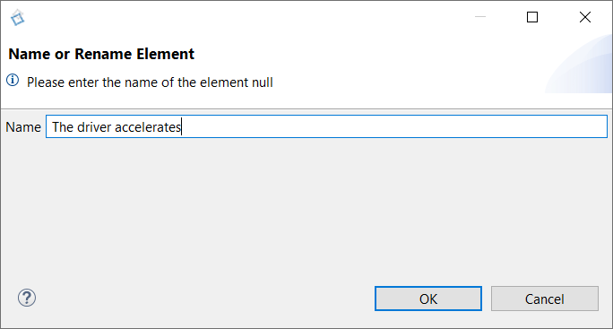
- Type the name of the user story: The driver accelerates
- Click on OK
- Double Click on the user story: The driver accelerates
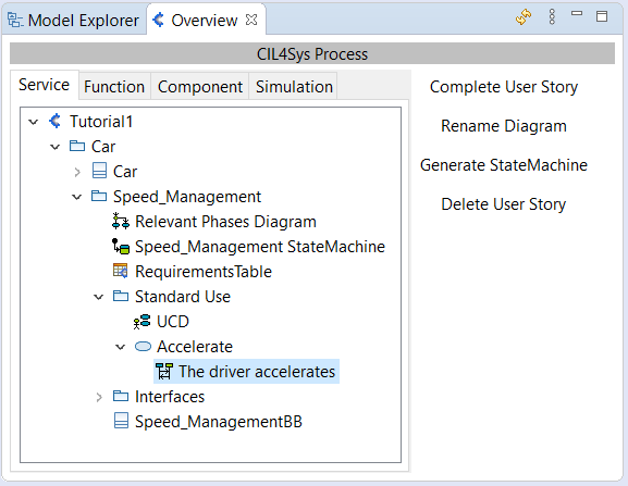
COMPLETE THE USER STORY
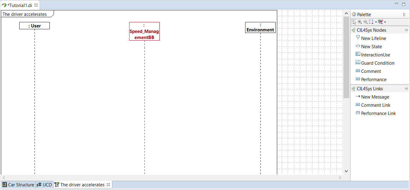
- Drag&Drop a New State on the Speed_Management Service lifeline
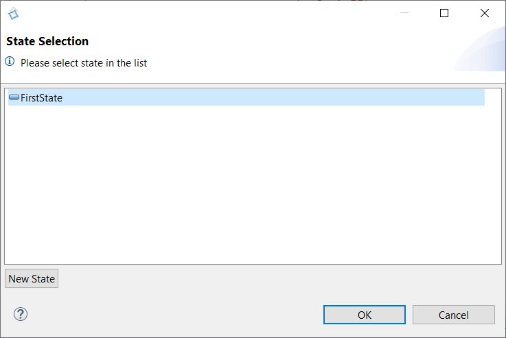
- Select FirstState
- Click on OK
- Rename the state after creation (in Active). You can do it just after the creation or by the Properties view of Papyrus
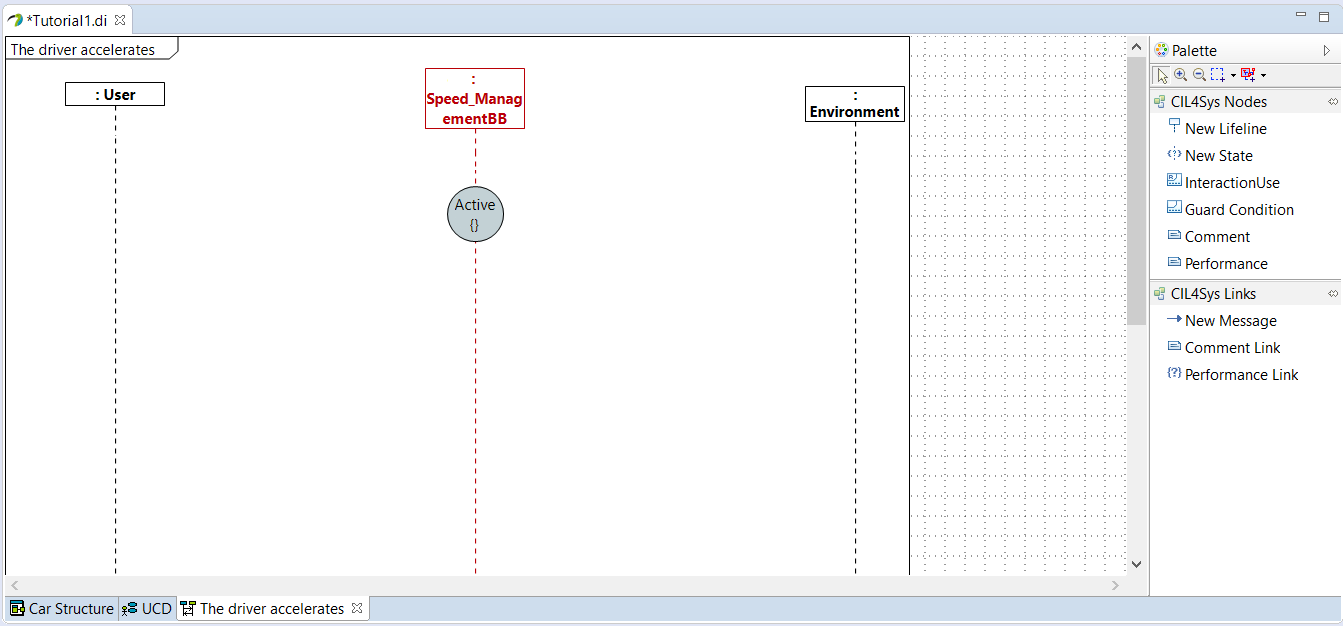
- Trace a New Message between the user and the service
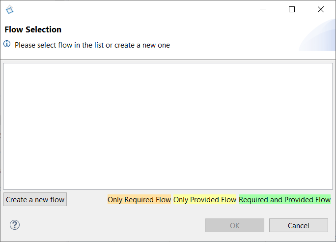
- Click on Create a new flow

- Drag&Drop a New Interface on the diagram
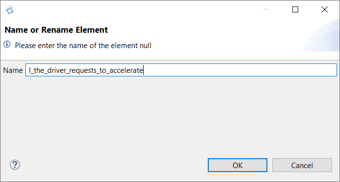
- Type the name of the interface: I_the_driver_requests_to_accelerate
- Click on OK
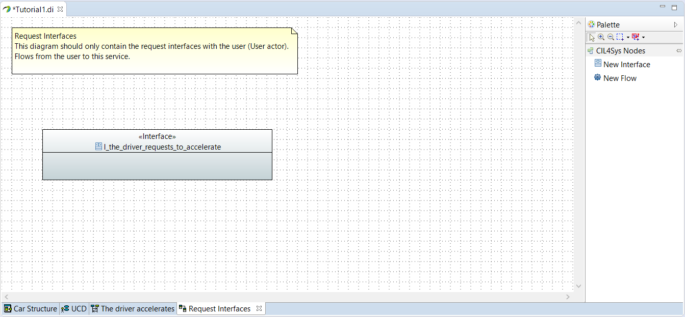
- Before creating a new flow in the interface, we need to create a new data type AccelerationType
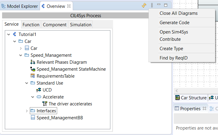
- Click on the View menu button in the CIL4Sys Overview
- Click on Create Type
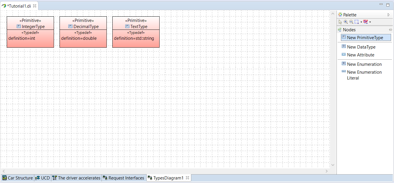
- Create a New PrimitiveType
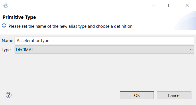
- Type the name: AccelerationType
- Choose the type: DECIMAL
- Click on OK
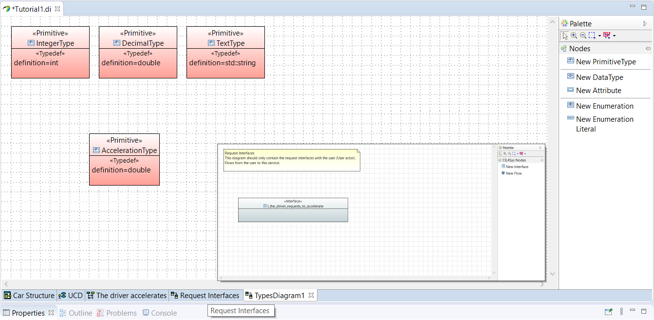
- Go back to the Request Interfaces diagram by clicking on the tab Request Interfaces
If you have closed the diagram previously, you can still get back to it via the CIL4Sys overview in the Interface package
- Drag&Drop a New Flow in the newly created interface
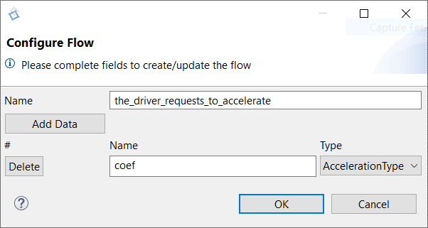
- Type the name
- Click on Add Data
- Type the name of the data: coef
- Select the type of the data: AccelerationType
- Click on OK
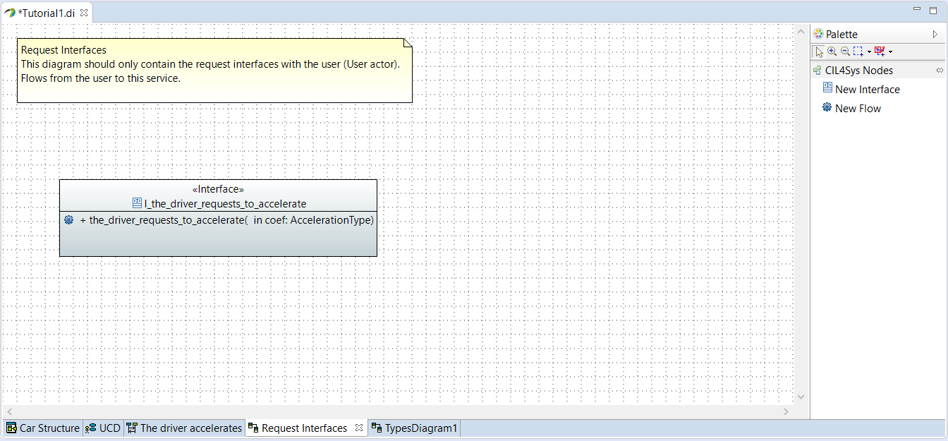
- Go back on the user story
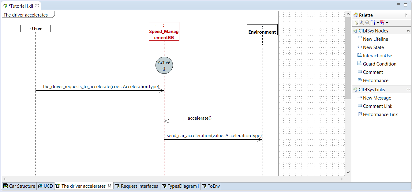
- Trace a New message between the user and the service
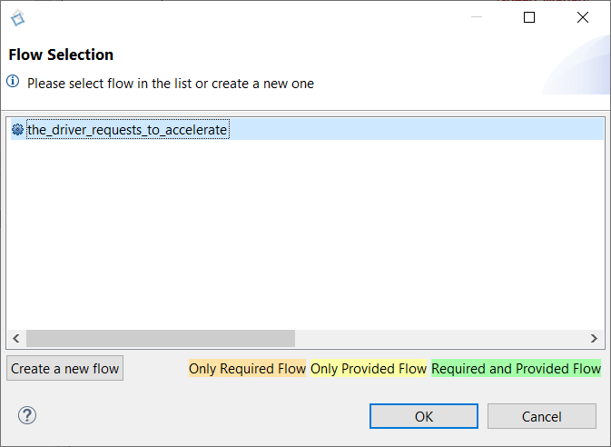
- Select the newly created flow
- Click on OK
- Trace a message between the service lifeline on itself (internal activity)
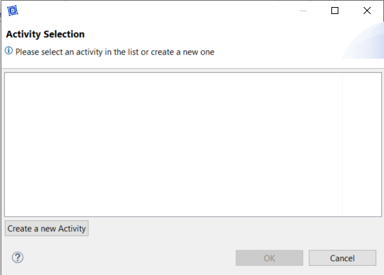
- Click on Create a new activity
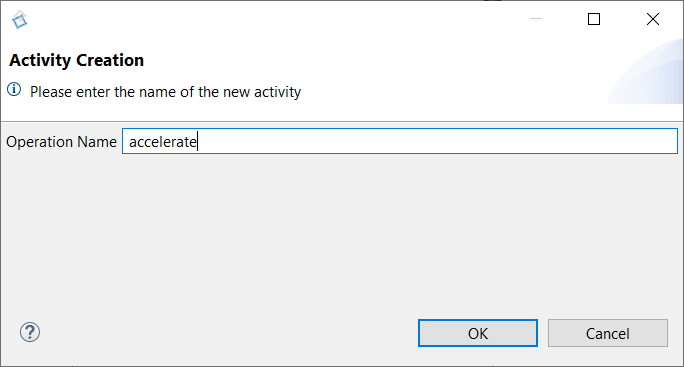
- Type the name of the activity: accelerate
- Click on OK
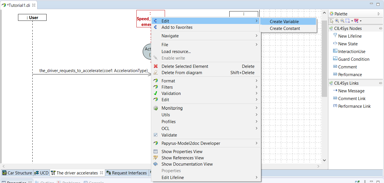
- Right-click on the service lifeline
- Select Edit > Create Variable
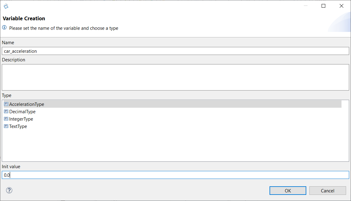
- Type the name of the variable: car_acceleration
- Choose the type: AccelerationType
- Set an init value: 0.0
- Click on OK
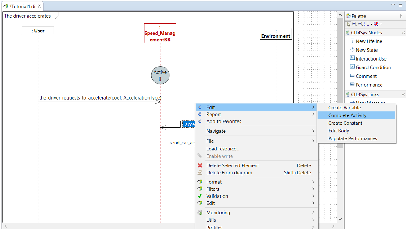
- Right-click on the accelerate activity
- Choose Edit > Complete Activity
- Select C++ Code
- Click on Next
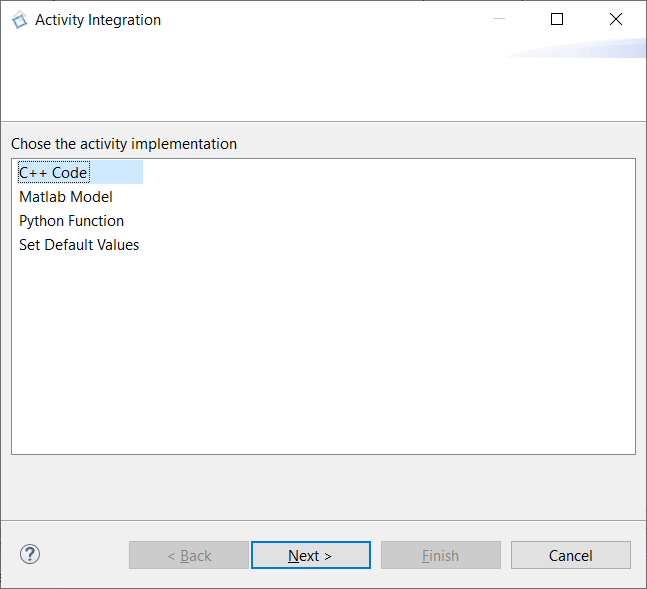
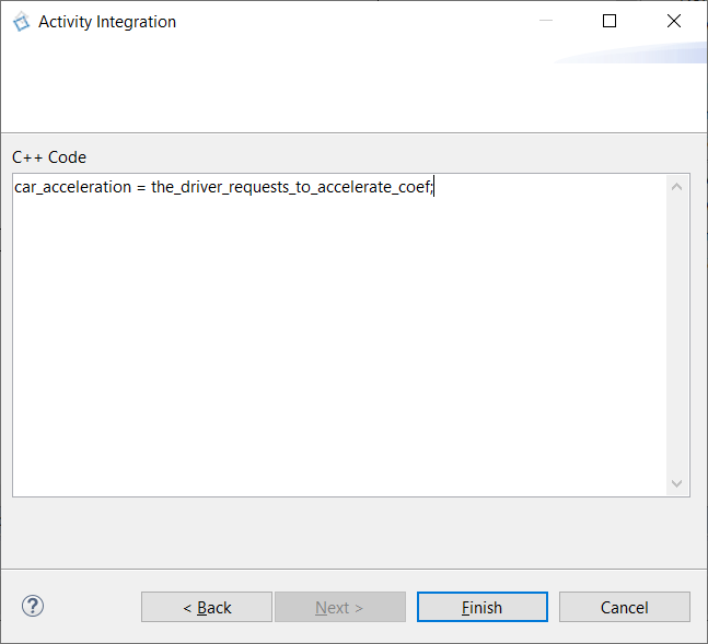
- Type the code to accelerate: car acceleration = driver request acceleration (with both accelerations in m/s²)
car_acceleration = the_driver_requests_to_accelerate_coef;
- Click on Finish
- Trace a New Message between the service and the environment
- Click on Create a New Flow
- Drag&Drop a New Interface on the diagram
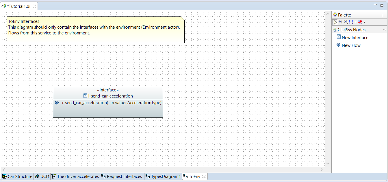
- Type the name of the interface: I_send_car_acceleration
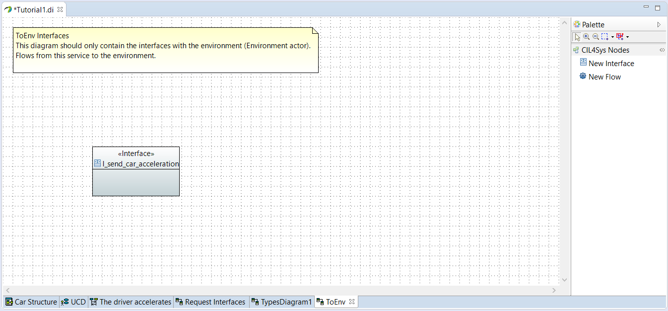
- Drag&Drop a New Flow in the newly created interface
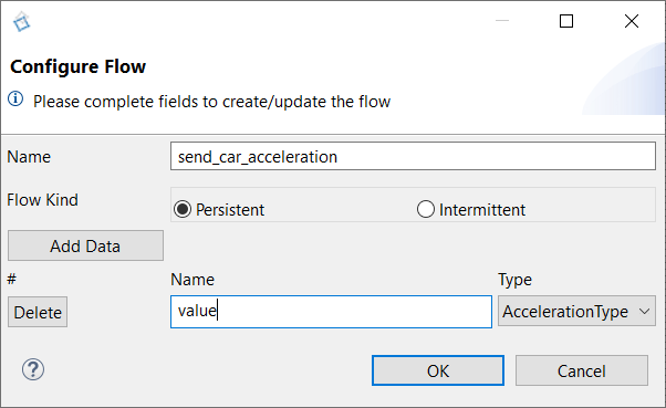
- Type the name: send_car_acceleration
- Click on Add Data
- Type the name of the data: value
- Select the type of the data: AccelerationType
- Click on OK
- Go back on the user story
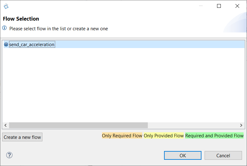
- Trace a new message between the service and the environment
- Select the newly created flow
- Click on OK
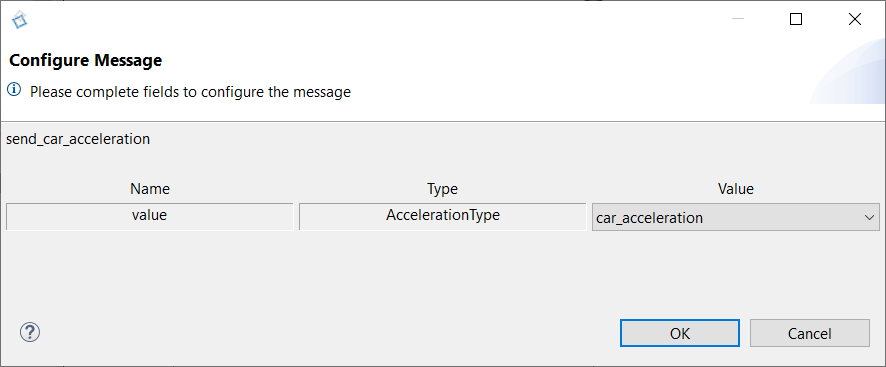
- Select the data value: car_acceleration
- Click on OK
- Select the user story in the CIL4Sys Overview
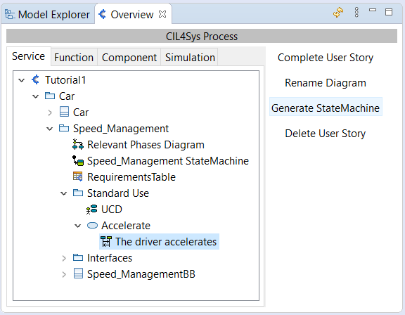
- Click on Generate State Machine
- Click on Ok in the confirmation dialog box
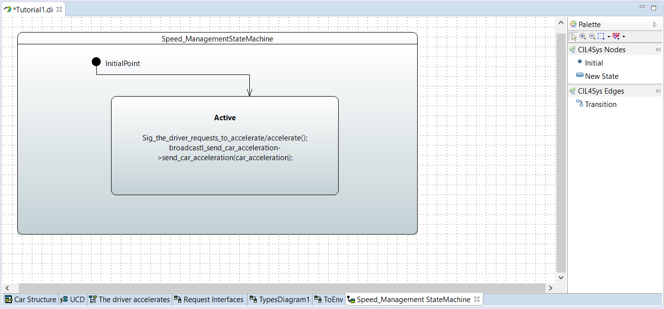
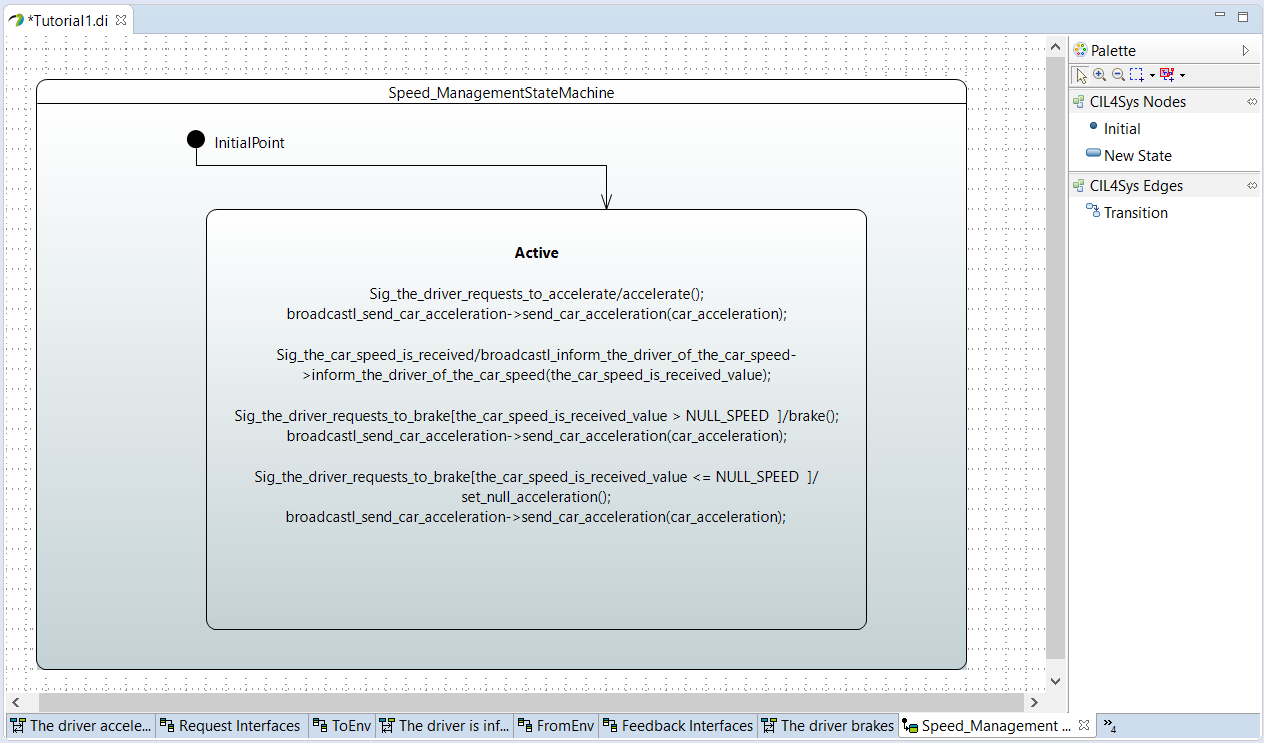
Regenerate the state machine after each change in diagrams. You should find in the state machine everything that you have written in the diagrams. The state machine helps you to check the model consistency. It is also essential for the simulation to work.
TO GO FURTHER
For your future projects you should :
- Use the same project structure: project > products > services > life phases > use cases > user stories. One project can have several products, one product can have several services, and so on.
- Use types (as AccelerationType) to clarify the type of information you want to exchange in your model, it’s a tool to help you even if you find it useless at the beginning of the training, it is a good work habit.
In the following, we are going to apply the same steps to create other usecases.
USECASE "INFORM OF CAR SPEED"
- Click on the View menu button on the CIL4Sys overview
- Click on Create Type
- Click on Create a new primitive type
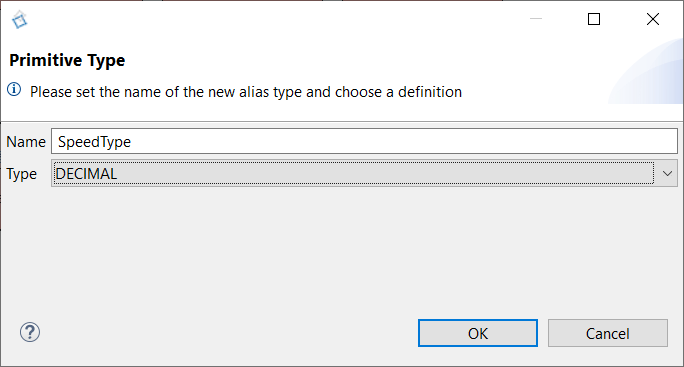
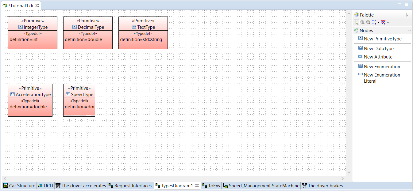
- Type the name: SpeedType
- Choose the type: Decimal
- Click on OK
- Select Standard Use Package in CIL4Sys Overview
- Click on Complete Use Cases
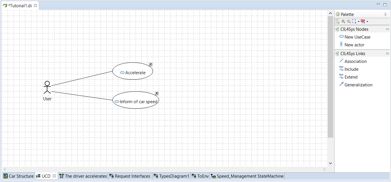
- Drag&Drop a New UseCase on the diagram
- Type the name of the new use case: Inform of car speed
- Click on OK
- Trace an association between the actor and the newly created use case
- Select the use case Inform of car speed in the CIL4Sys Overview
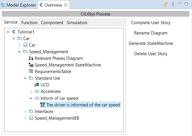
- Click on New User Story
- Type the name of the user story: The driver is informed of the car speed
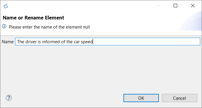
- Click on OK
- Double Click on the newly created user story in the CIL4Sys Overview
- Drag&Drop a New State on the service lifeline
- Select Active
- Click on OK
- Trace a message between the environment and the service
- Click on Create a new flow
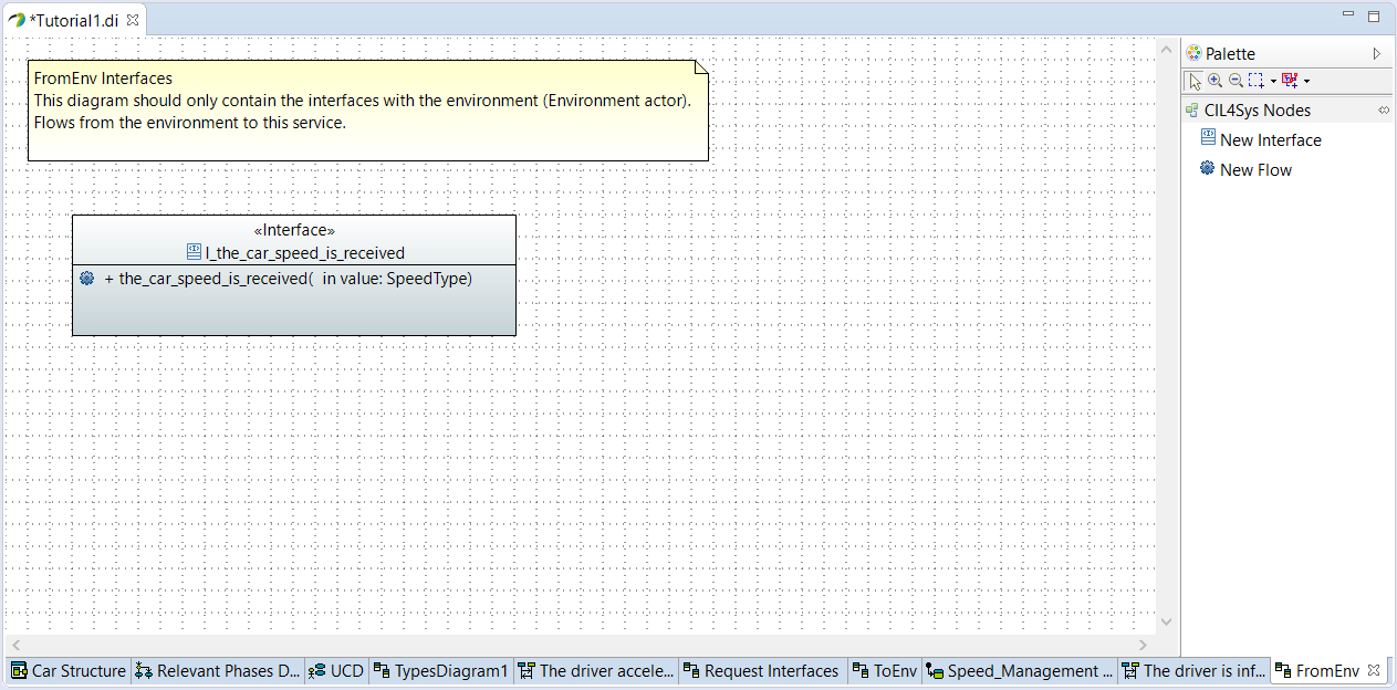
- Drag&Drop a New Interface on the FromEnv Interfaces diagram
- Type the name of the interface: I_the_car_speed_is_received
- Click on OK
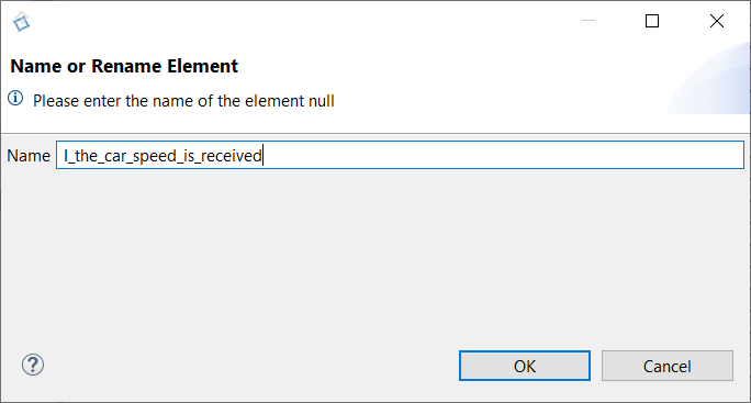
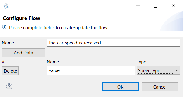
- Drag&Drop a New flow in the newly created interface
- Type the name: the_car_speed_is_received
- Click on Add data
- Type the name: value
- Set the type of the data: SpeedType
- Go back on the sequence diagram
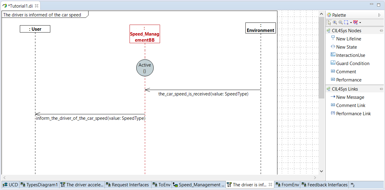
- Trace a message between the environment and the service
- Choose the_car_speed_is_received
- Trace a New Message between the service and the user
- Click on Create a New Flow
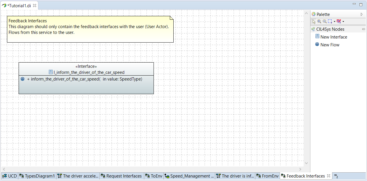
- Drag&Drop a New Interface on the Feedback Interfaces diagram
- Type the name of the interface: I_inform_the_driver_of_the_car_speed)
- Click on OK
- Drag&Drop a New flow in the newly created interface
- Type the name: inform_the_driver_of_the_car_speed
- Click on Add data
- Type the name: value
- Set the type of the data: SpeedType
- Go back on the sequence diagram
- Trace a message between the service and the user
- Choose inform_the_driver_of_the_car_speed
- Click on OK
- Select the value: the_car_speed_is_received_value
- Click on OK
- Select the user story in the CIL4Sys Overview
- Click on Generate State Machine
- Click on Ok in the confirmation dialog box
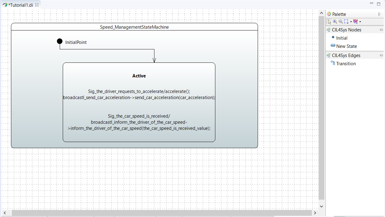
USECASE "BRAKE"
- Select Standard Use Package in CIL4Sys Overview
- Click on Complete Use Cases
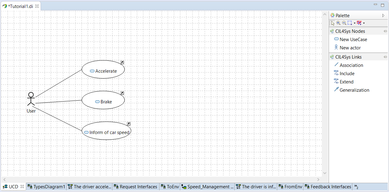
- Drag&Drop a New UseCase on the diagram
- Type the name of the new use case: Brake
- Click on OK
- Trace an association between the actor and the newly created use case
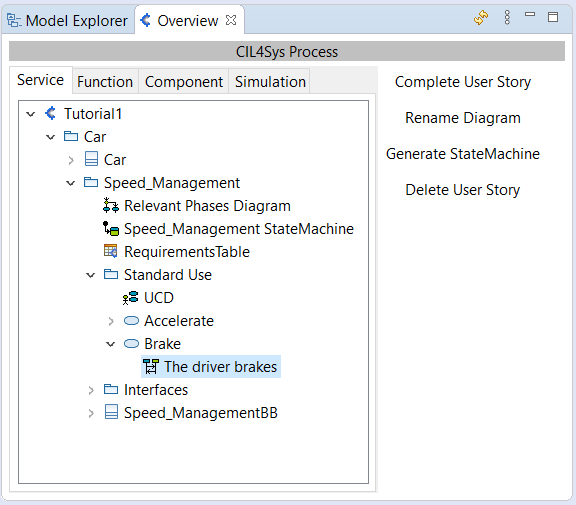
- Select the use case Brake in the CIL4Sys Overview
- Click on New User Story
- Type the name of the user story The driver brakes
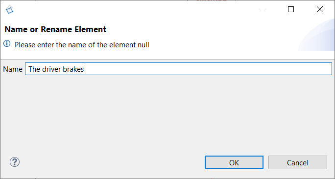
- Click on OK
- Double Click on the newly created user story in the CIL4Sys Overview
- Drag&Drop a New State on the service lifeline
- Select Active
- Click on OK
- Trace a message between the user and the service
- Click on Create a new flow
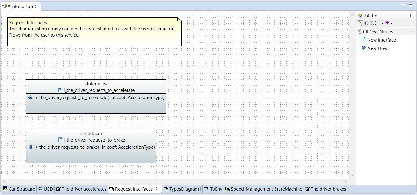
- Drag&Drop a New Interface on the Request Interfaces diagram
- Type the name of the interface: I_the_driver_requests_to_brake
- Click on OK
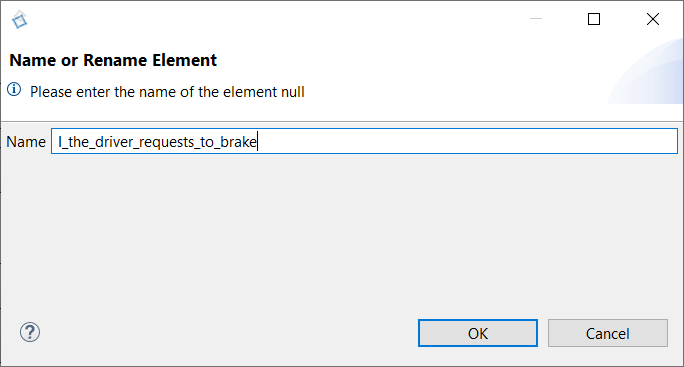
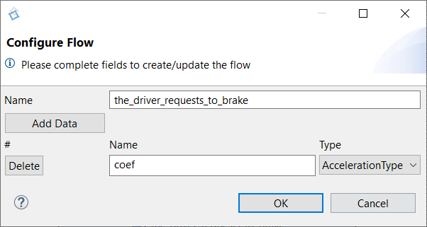
- Drag&Drop a New flow in the newly created interface
- Type the name: the_driver_requests_to_brake
- Click on Add data
- Type the name: coef
- Set the type of the data: AccelerationType
- Go back on the sequence diagram
- Trace a message between the user and the service
- Choose the_driver_requests_to_brake
- Trace a New Message between the service and itself
- Click on Create a New Flow
- Type the name of the flow: brake
- Trace a New Message between the service and the environment
- Choose send_car_acceleration
- Click on OK
- Select the variable car_acceleration to return
- Click on OK
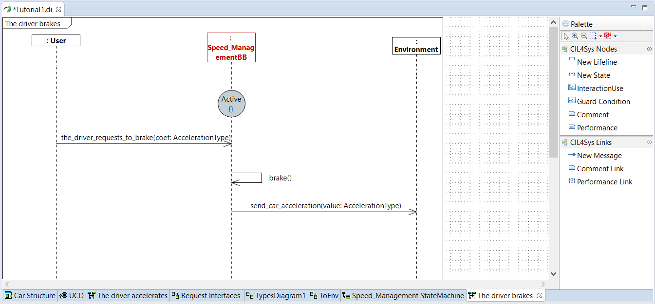
- Right-click on brake internal activity
- Right-click on the internal activity, Edit > Complete Activity
- Select _C++ Code _
- Click on Next
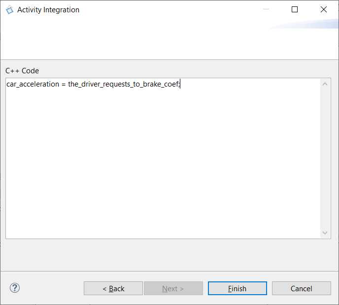
- Type the code to brake
car_acceleration = the_driver_requests_to_brake_coef;
- Click on Finish
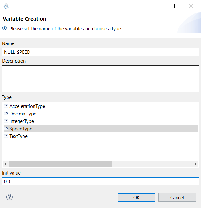
- Right-click on the service lifeline
- Click on Edit > Create Constant
- Type the name: NULL_SPEED
- Choose the SpeedType
- Set the initial value to 0.0
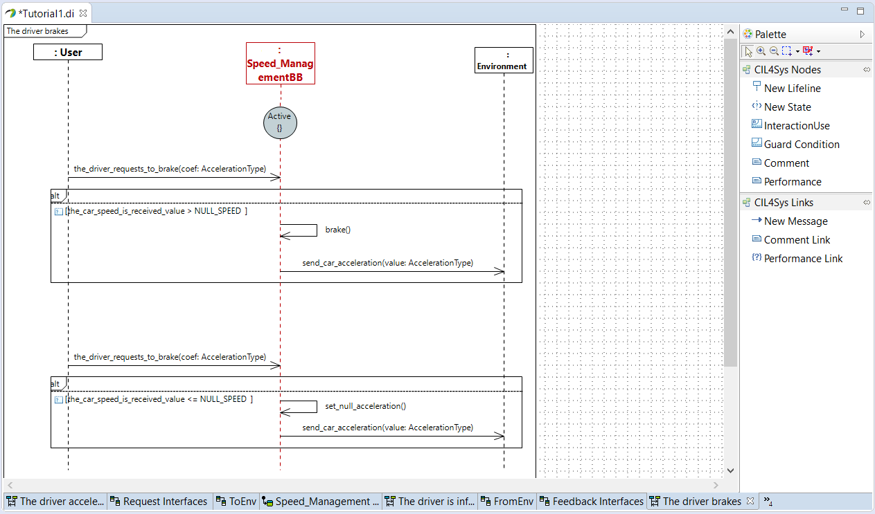
- Drag&Drop a Guard Condition on the diagram
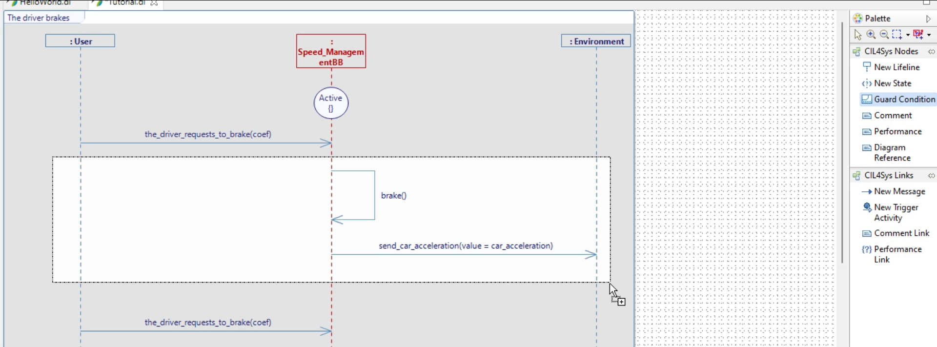
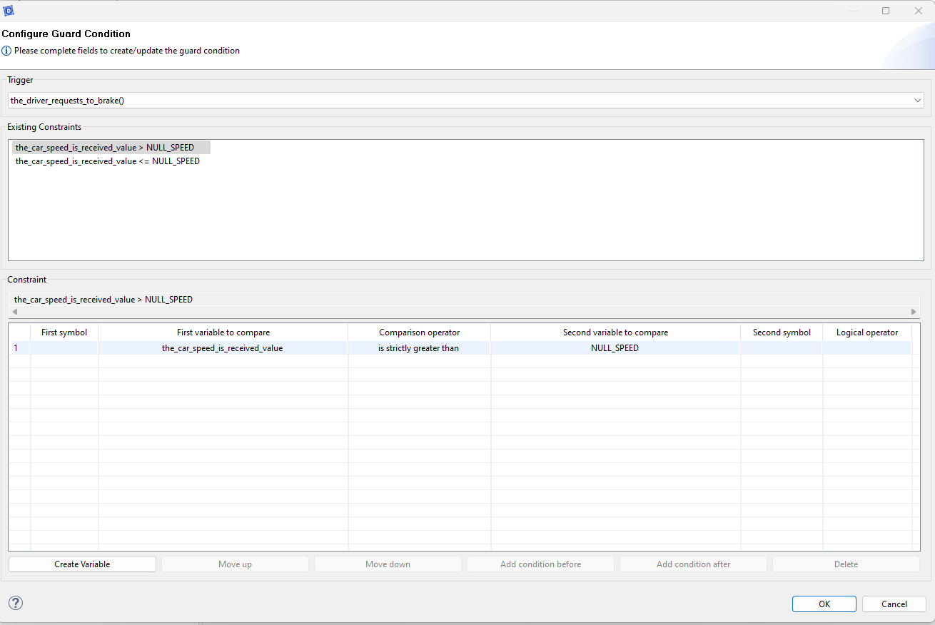
- Choose the trigger the_driver_requests_to_brake
- Set the condition as follow
- Complete the sequence diagram for the case where the speed is null (refer to previous steps if needed)
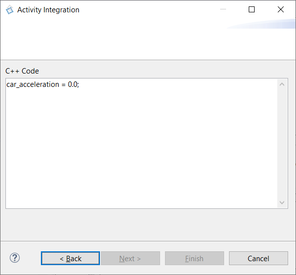
- Complete the internal activity set_null_acceleration
car_acceleration = 0.0;
- Select the user story in the CIL4Sys Overview
- Click on Generate State Machine
- Click on Ok in the confirmation dialog box
TO GO FURTHER
For this simple tutorial we consider only one state (Active). It is possible to introduce several states. You should try it by your own in a blank project:
- In a user story, begin with a state “Active” and draw some messages as we did before.
- End the user story by another state, “Turbo” for example.
- Generate the state machine: you should see the messages you wrote and a condition to go from the state “Active” to the state “Turbo”.
- You can also do it the other way around: to go from the state “Turbo” to the state “Active” with another user story.
GENERATE CODE
If you have the community version of Designer (free version), please build the executable via Hub4Sys as shown on this page
- Before generating the code, ensure that the CIL4SysLibs are already part of the project.

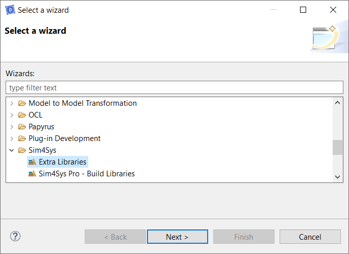
- If it's not the case, you must add the Libs in File > New > Other... In the new window, select Extra Libraries in the Sim4Sys folder. If you have a Pro access, you can add Sim4Sys Pro - Build Libraries instead:

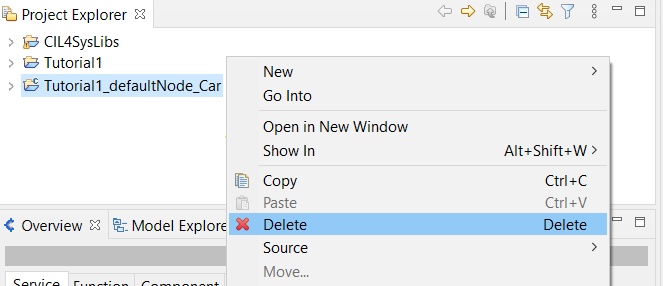
If you've already tried to generate the code without the CIL4SysLibs, you might not be able to compile even after adding the libraries. To reset everything, right-click on the generated code folder, and delete it.
Follow the next steps to generate the code.
- Click on the Overview menu, thanks to the following icon:

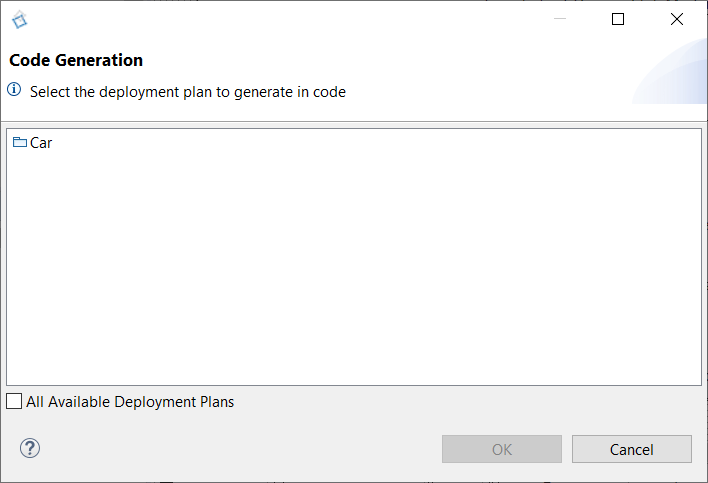
- Click on [Code] Generate and build in CIL4Sys Overview
- Select Car (or CarMainProduct)
- Click on OK
- Select Cygwin GCC (Cygwin 64 must be installed, for Windows only)
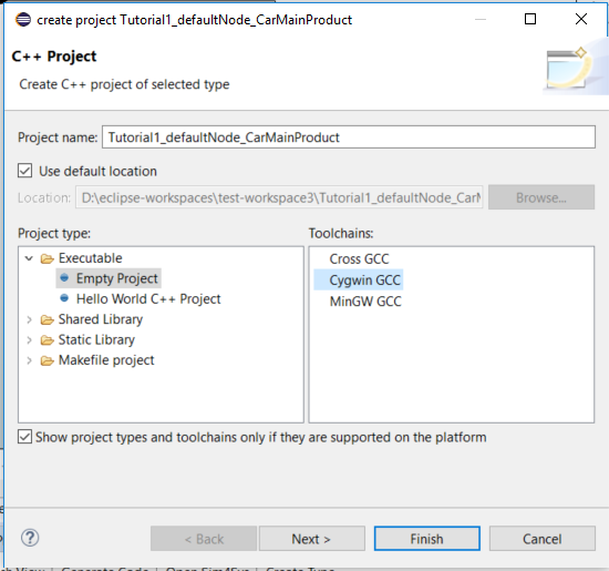
- Click on Finish
- Click on OK in the confirmation dialog box
- Right-click on the newly created C++ project
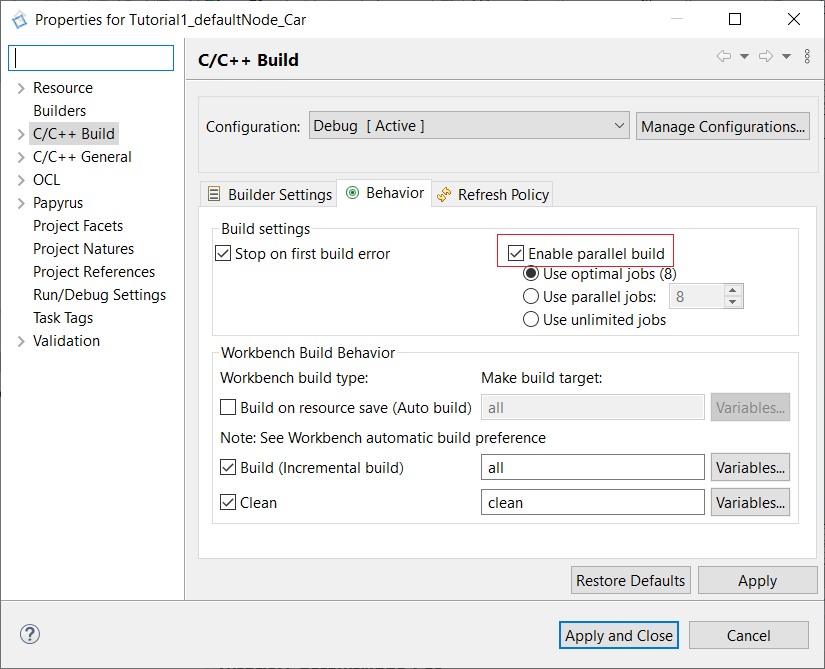
- Before building the project, you can right-click on it, and then select Properties. Then go into the C/C++ Build section, and in the Behavior tab. Here you can check Enable parallel Build. Apply and close. Now, the process of building will be much more efficient.
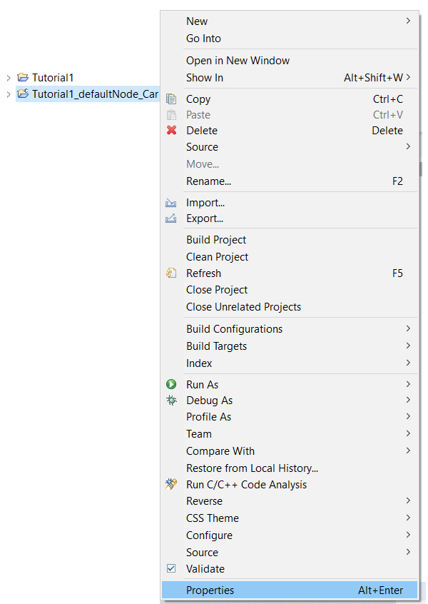
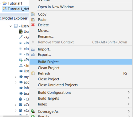
- Select Build Project (if the CIL4SysLibs are not imported yet, refers to the previous step before), then we can build our Car project.
-
In case you have an error with undeclared types, follow the following procedure:
- Go to Window > Preferences

- In Papyrus > C++ Code Generation, check Generate “using namespaces”
- Uncheck Use C++11 class enumerations
- Right-click on C++ project
- Select RunAs > C/C++ Application
- Switch back to your Virtual Bench project.
MAPPING (ACCELERATION)
-
Go on the Sim4Sys Virtual Bench: https://sim4sys.com/
-
Identify with your login and password
-
In the Projects tab choose your sandbox project

If you don't have a sandbox, you can create one by clicking on New Project. Then, in the Project name field, you can write "Sandbox your name" and in the Project URL field, "sandbox".
- Then in the sandbox tab, open the Executables folder, in which you can add a new executable by clicking on

- Name it and press ok.

-
Now you need to import types and flows from the model to the virtual bench. To do that, follow the steps in this paragraph.
-
Back in the Executable folder, expand your new executable. For this, you can click on the small black arrow on the left side of the folder, or you can directly double-click on the folder itself.
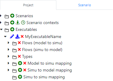
-
Add Scenario contexts by clicking on the + sign. For this tutorial, we will need 3 contexts: HMI, Scene2D and Timeline (see here for more information).
-
Then, add a new scenario

- Name it as you wish (accBrake, tuto1...), and press Ok. The new scenario should now be opened.
To open a scenario you can double click on the scenario's name or click on the eye next to the scenario's name.

- In your scenario tab, Add a new WebSocket.
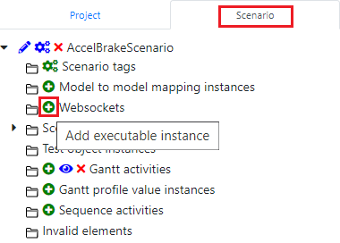
- As an executable, select the one you’ve created before (here AccBrakeTuto1), you can name it as you want, and press Ok.

Simu to model mapping_ is the part where we manage how the simulation will interact with the model that we’ve created with _Papyrus.
Mapping for the flow the_driver_requests_to_accelerate mapping
Now let’s map the flow the_driver_requests_to_accelerate. To do that, see the following steps:
- Add a Simu to model mapping element by clicking the + sign:
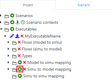
What we want to do is to create a Timeline action, that is, an element that will maintain one action over a certain period of time. Here we will use this to accelerate.
- Select the Timeline Action element to interact with the model. And choose the the_driver_requests_to_accelerate flow:
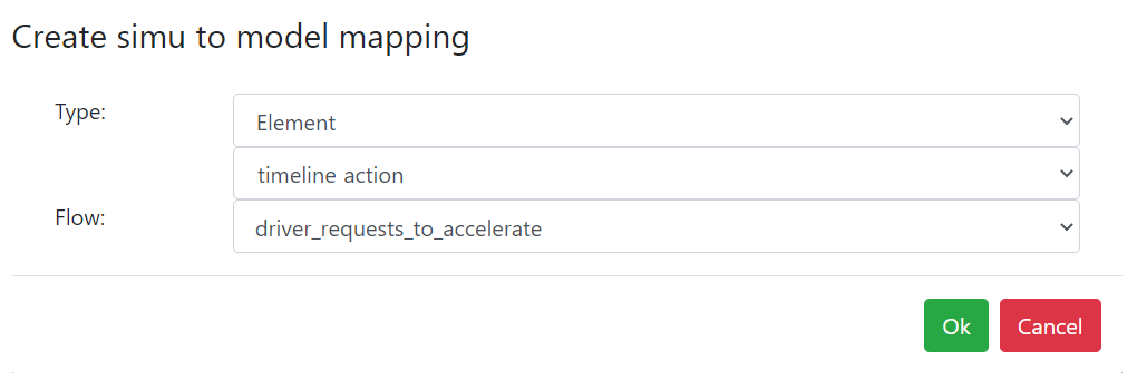
- Select the value parameter to be transmitted when the Timeline action will be started:

We need to create the element that will be linked to this mapping.
- Switch to Edit Mode if you are in Run Mode, by clicking on the button:

- In Edit mode, in the context menu below, select the timeline context (don't forget to add a timeline context before that):

The timeline context is where you can visualize your story through the time and the timeAxis element is already placed in this context.
- In this menu Drag&Drop the Timeline background element:
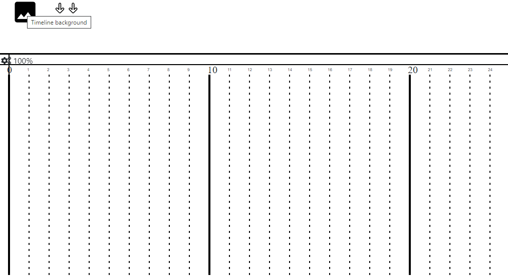
You may have to change the context, then return to the timeline for the layout to refresh.
This will help you visualize the time during the Run.
- Drag&Drop the Timeline action:
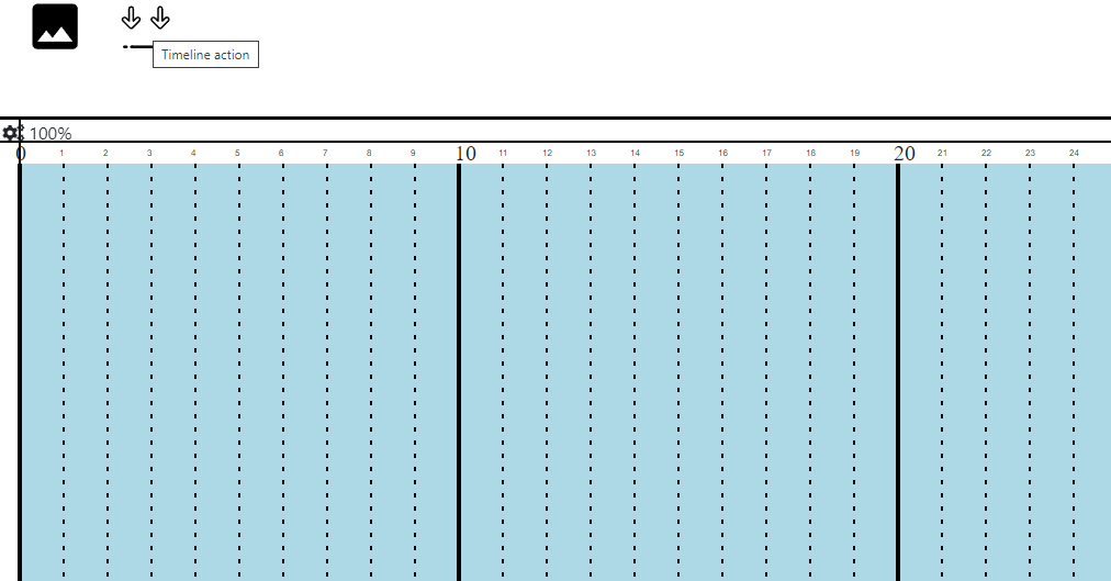
If you ever want to move an element, you can drag it with your mouse, by pressing the Alt key on your keyboard.
You can also zoom/dezoom on the context by pressing the Alt key and scrolling with the mouse wheel.
- Right-click on the action and select Send flow:
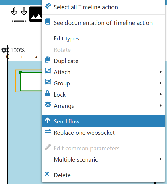
- Click on Reuse:

- Select the correct items and click on Ok:

Now, we need to define the acceleration value that will be transmitted to the model.
-
Double click on the Timeline action element,
-
Check the checkbox as shown below on the Value parameter line and click on the right blue button
 :
:

- Add a new line by clicking on the + button and fill the value fields with the acceleration coefficient you want to accelerate the car, as shown belown:
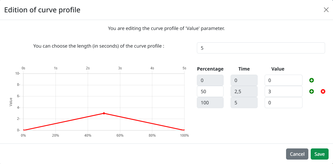
- Click on Save to Save the modifications of Curve Profile
Mapping for the flow the_car_speed_is_received mapping
We need to create the simu to model mapping for the speed flow sent to the model (the_car_speed_is_received).
We will see another way to create and add a mapping at the same time:
- In Edit Mode, in the context menu below, select the scene2D context. This context is a 2D top view representation of the simulation.

- In this menu, to the right, Drag&Drop the roadPavement element:
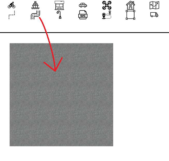
- Double click on the element. Click on Edit Path (blue button) to modify the path value as shown below:

- Set 800 meters on x direction, as bellow. And click on OK.

-
Click on Save.
-
Select Users and Drag&Drop the Car element on the context:
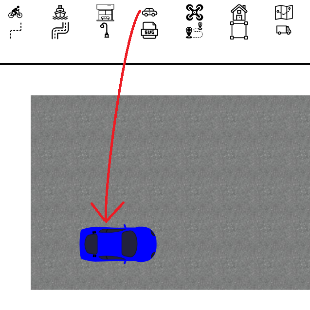
- Right-click on the Car element and select Send flow:
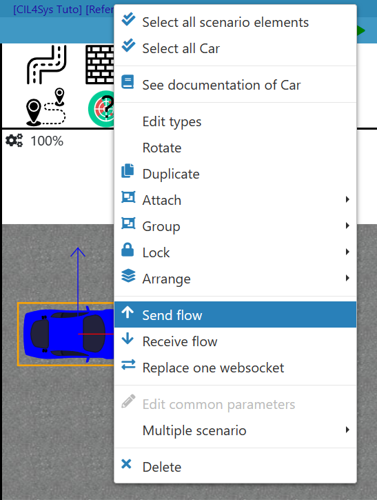
- Click on Create:

- Select the flow the_car_speed_is_received:

- Select the speed parameter to be the data that is transmitted by the flow.

Mapping for the flow send_car_acceleration
Now, we will use the same Car element to receive the car acceleration value from the model. The process is very similar.
Still in the executable folder, find Model to simu mapping.
- Add a new one:
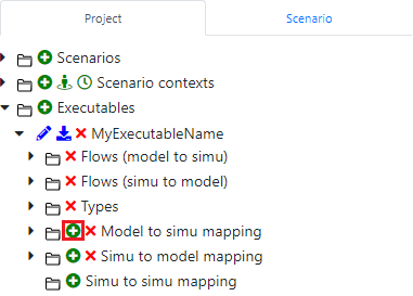
- Select the Car element,
- Select send_car_acceleration as a flow:

- Now, you need to indicate that the value you want to display is the one called value in your flow:

- In Edit mode, select the scene2D context,
- Right-click on the car element and select Receive flow mapping, then click on Reuse:
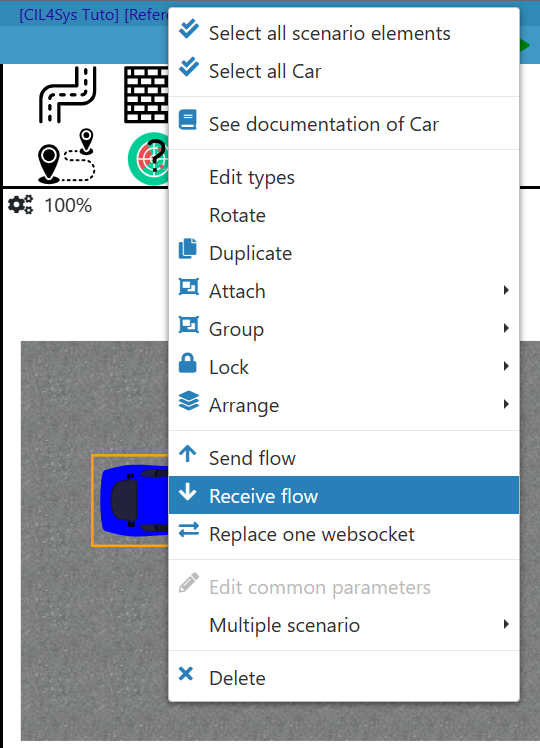
- Click on OK:

Mapping for the flow inform_the_driver_of_the_car_speed
Finally, we will create the other model’s output, a gauge in which we can see the current speed of our car.
Still in the executable folder, find Model to simu mapping.
- Add a new one:

- Select the correct element, which is of type gauge,
- Select inform_the_driver_of_the_car_speed as a flow:

- Now, you need to indicate that the value you want to display is the one called value in your flow:
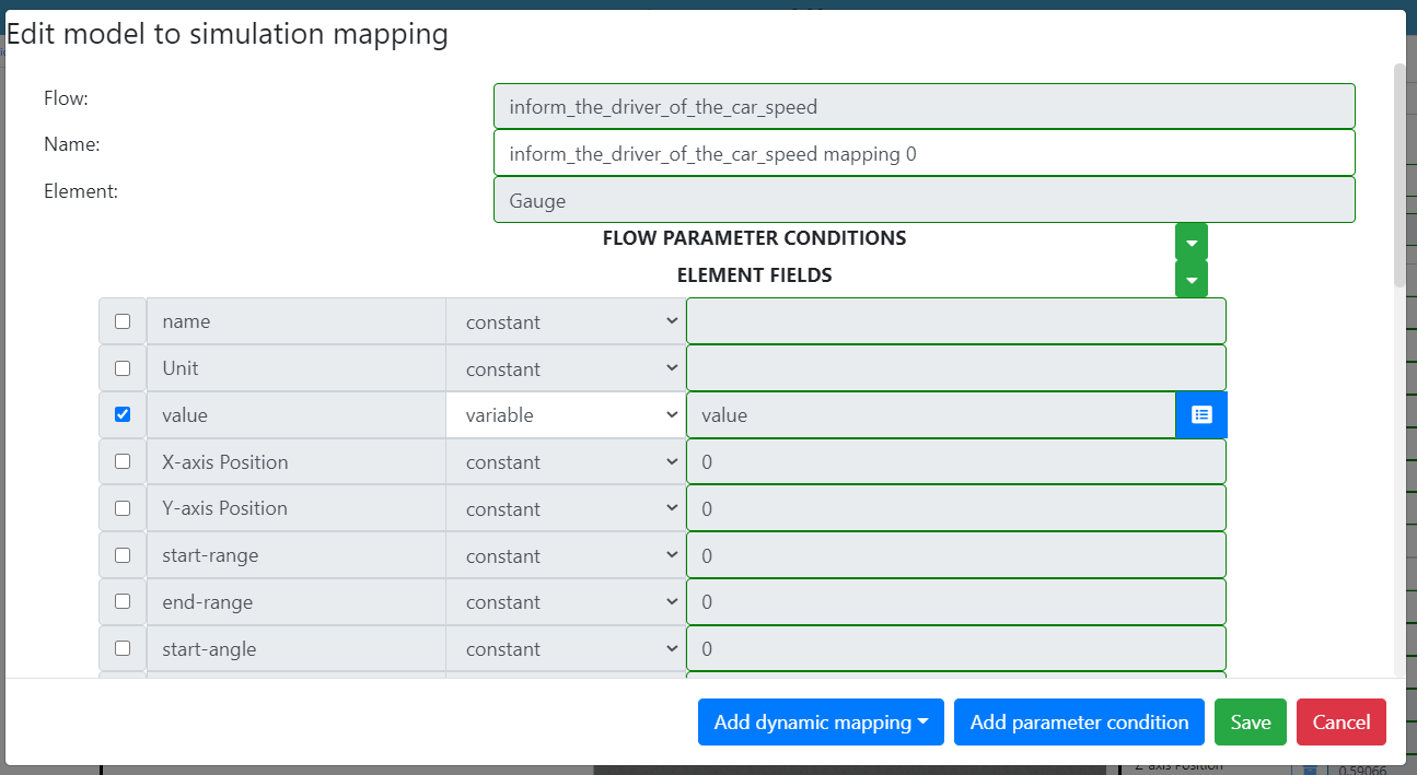
- In Edit Mode, select the HMI context. This context is the representation of the control panel of the car:

-
Drag&Drop the Gauge
 in the context.
 -
Right-click and select Receive flow:
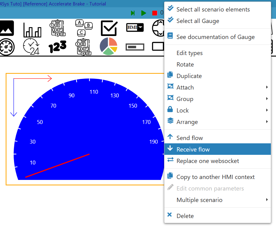
- Click on Reuse:

Now everything should be linked. Switch back to Designer.
You can set a context as the main context:
Switch to Run mode, then Right click on the desired context and Define as main context
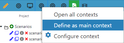
MAKE IT WORK
- In Virtual Bench, next to the executable you have created, click on the cog
 . A pop-up window will appear, type the path of the executable you have generated with Designer. The executable should be in the Debug file of the DefaultNode folder.
 - Launch this executable, by double-click on it.
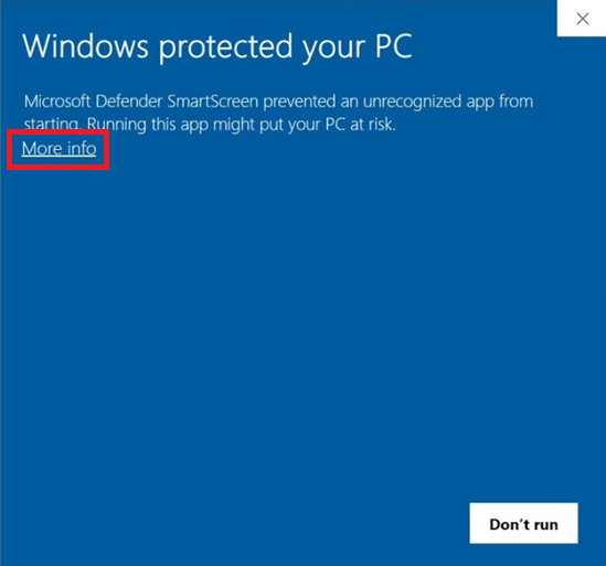
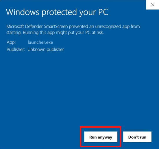
When running the executable for the first time, windows might try to prevent it from being executed. In order for it to run now and for each future executions, when the following popup appears, click on "More info", then click on the "Run anyway" button.
- Switch to Run Mode by clicking on the pencil button
 located on the top left of the page.
 - While your Designer project is running, connect the WebSocket by clicking on websocket connection buttons located on the top-right. It will switch from the red color to the green color.

If you don't see the websocket button please change the preference
You can open the contexts where you have added elements for the simulation. Each context will be opened in a dedicated window.
- For instance, open the Cluster context. This will open a window.
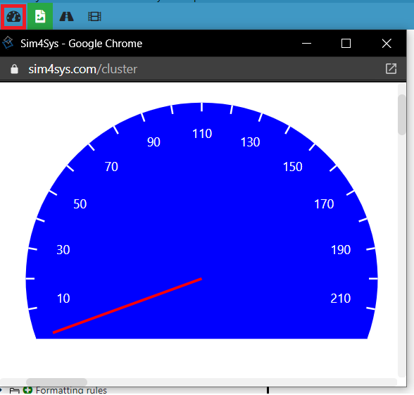
-
Click on the Play ► button. It will bring all the opened contexts windows in the foreground automatically.
-
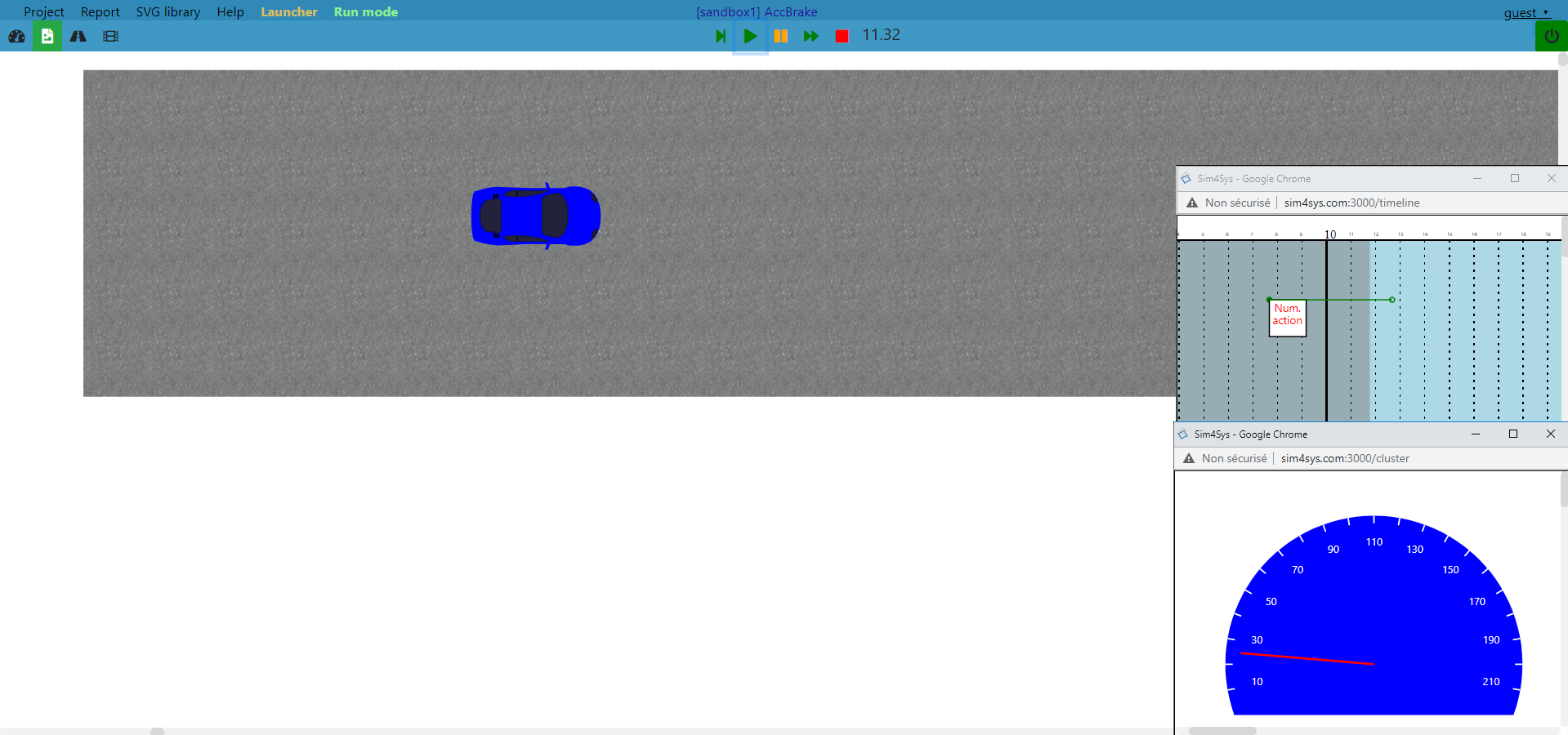
Follow the timeline, and check if it works, it should speed up.
Below is an example with the cluster and timeline contexts opened simultaneously with the scene2D on the main window. You can see that the speed gauge raises and the car is moving on the scene2D context:
MAPPING (BRAKE)
To complete everything, let’s add the brake’s mapping.
Following the same steps as for the accelerator’s mapping:
- In your Executable’s folder, add a new Simu to model mapping.
- As for the accelerator, select a Timeline action, but select the flow driver_requests_to_brake.

- Select the value parameter to be transmitted when the Timeline action will be started.

-
Now back into the Edit Mode, in the timeline context, Drag&Drop another Timeline action after the previous one to brake, just after the acceleration.
-
Add the flow driver_requests_to_brake to the new Timeline action.
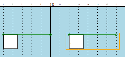
- As for the accelerator, follow the same steps to modify the curve profile of the TimelineAction element, in order to define the decceleration coefficient:
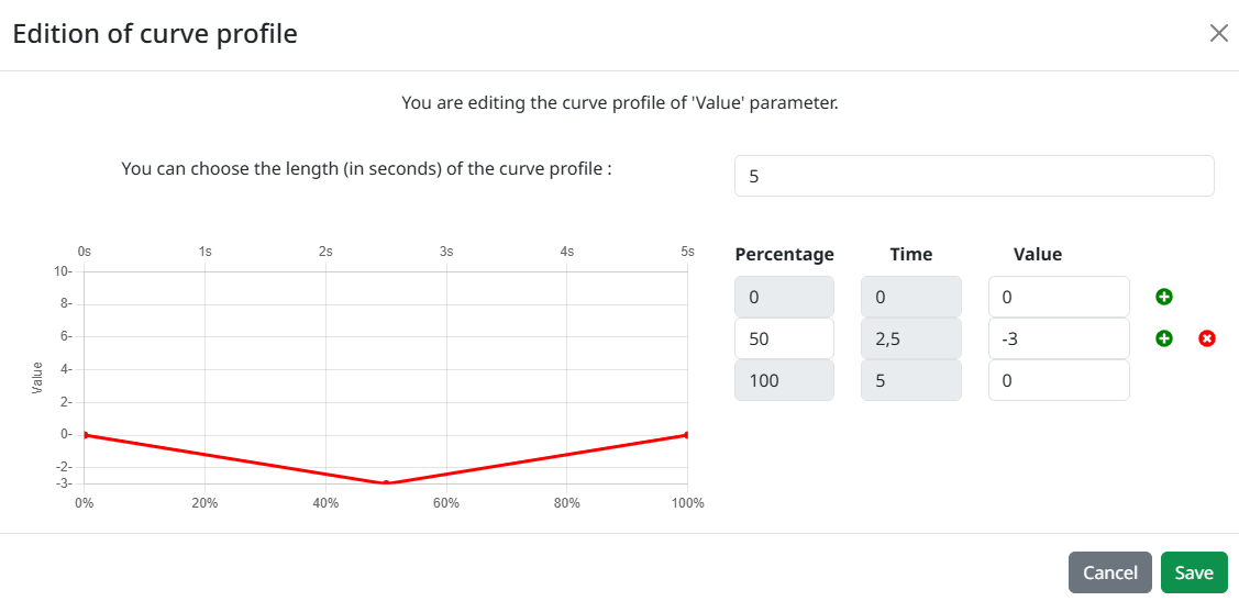
With the upper diagram, we can check if our brake is working, but we won’t be able to check if it will stop at 0, as created in the model. For this to be checked easily, we can lengthen the period of time of our braking Timeline action.
- For this, double click on the Timeline action. You should see a menu opening.
- Increase the Duration value to make it longer.
- Then, press Save.

- Now, your timeline should look like the picture below:

You can now check everything in Run Mode. Run your papyrus model as in the previous steps. Enable the WebSocket button, press play, and look at both the timeline and the cluster context.
You should notice the acceleration, the deceleration, and the needle stopping at 0. In case this part is not managed, the speed will be negative and will result in displaying the absolute speed (the gauge will therefore display an increasing speed after hitting zero while braking). If it just stops at 0, it works.