Include a matlab activity in a model
PRESENTATION
This tutorial can be done from the Start to use Sim4Sys with a simple model (blackbox) model of car.
Prerequisites
- Have done the tutorial Start to use Sim4Sys with a simple model (blackbox),
- Concept on C++.
News skills that you will acquire
On Designer:
- Import a Matlab and use its function,
- Use variable with a multiplicity *,
- Use a periodic flow "when",
- Include external libraries,
- Build Configuration Edition.
On Virtual Bench:
- Use continious triggers,
- Concept on "Clock",
- Create mappings with a list,
- Use a new Context elements: Decorative elements (e.g. a pedestrian crossing), Polysensor.
Duration
4h
INTRODUCTION
In this tutorial we're going to handle an emergency braking. When getting closer to an obstacle such as a pedestrian or another car, we want the car to brake without the user's action. We already have a service called SpeedManagement. This service takes requests into account, and brake or accelerate according to those. In our new implementation, we want to :
- Detect close elements.
- Determine if the speed and the distance to those elements are safe.
- Brake accordingly.
Within these 3 steps, we only request to brake in the last one. Therefore, the idea is to create a new service, called EmergencyBrakeManagement which asks the SpeedManagement to brake when it needs to.
USING MATLAB
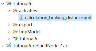
In this tutorial, we will be using a matlab file which will determine the braking distance of the vehicle. In order for papyrus to "understand" this matlab file, you will be given a .xml file which describe the inputs and outputs of the matlab function. This is what papyrus will use to map the file into your model. In our case, the file is called calculation_braking_distance.xml (you can find it in the ExtraLibs resource pack : New > Other > Sim4Sys > Extra Libraries), and needs to be placed into the folder of your project (In our case, ".../Tutorial6/") for it to work. It is good practice to create a special folder for activities description like this .xml file. As an example, you can store it in a new folder as "...Tutorial6/activities/". By refreshing the view of your project's folder in papyrus it should look like this:
CREATE A NEW USE CASE
We first need to create the EmergencyBrakeManagement service
- Open the Car Structure diagram, in which all services are displayed.
- Add a new service in the diagram, and name it EmergencyBrakeManagement.
- In the new service, open the Relevant Phases Diagram, and add new Standard Use life phase in the diagram.
We can now add a new use case
- Go into the new UCD diagram.
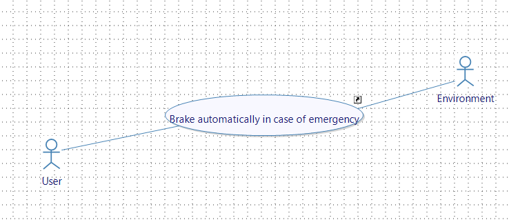
- Create a New Use Case "Brake automatically in case of emergency"
- Add the needed users
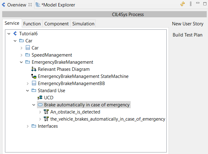
- In this newly created usecase, add two user stories :
- "An_obstacle_is_detected"
- "the_vehicle_brakes_automatically_in_case_of_emergency"
CREATE NEW TYPES
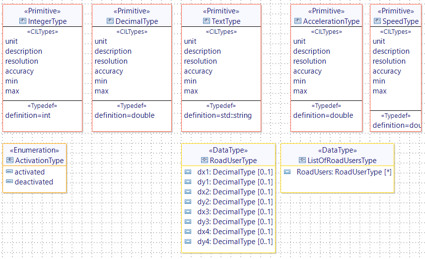
- Before completing the user stories, create three new types:
- a DataType RoadUserType, with eight Decimal attributes dx1, dy1, dx2, dy2, dx3, dy3, dx4 and dy4
- a DataType ListOfRoadUsersType, with a RoadUserType attribute RoadUsers (choose Many for Multiplicity parameter)
- an Enumeration ActivationType, with two Enumeration Literal deactivated and activated
CREATE NEW FLOWS AND INTERFACES
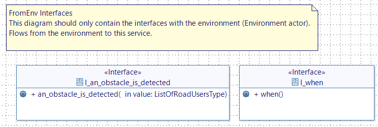
- Open the FromEnv diagram of the EmergencyBrakeManagement service.
- Create two new interfaces (I_an_obstacle_is_detected and I_when) with two new flows (an_obstacle_is_detected and when) as shown below (be careful with the arguments of these new flows !):
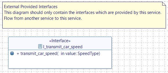
In order for our new service to have all the necessary information, we need to get the speed of the vehicle. This data is acquired in the SpeedManagement service. Therefore we need to transmit this speed data from the SpeedManagement service to the EmergencyBrakeManagement service. For this we will have to go back to the diagram called "The driver is informed of the car speed" in the SpeedManagement service. In this diagram we already have the speed received from the simulation. In the below step we will transmit this speed:
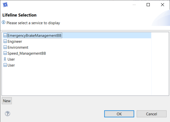
- Add a new lifeline on the diagram.
- Select EmergencyBrakeManagementBB service.
-
Then, click OK.
-
Go back to the diagram, and add a state.
-
Then trace a flow going from the SpeedManagement lifeline to the EmergencyBrakeManagement
-
Add the following interface:
You should now have a diagram like this one:

USER STORY An_obstacle_is_detected
- Go back to the EmergencyBrakeManagement service.
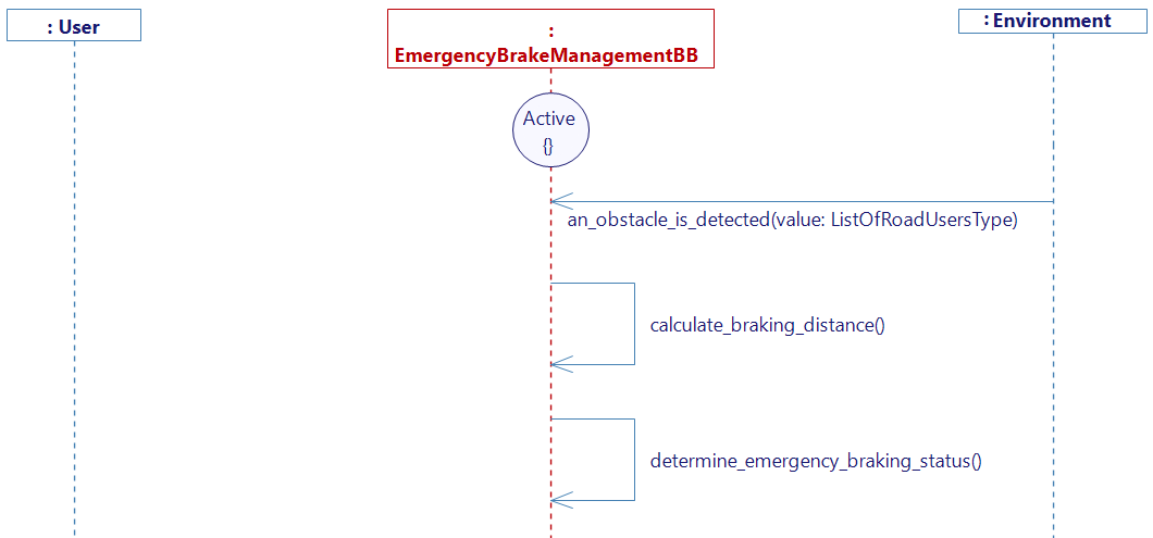
- In the Overview tab, double Click on the user story An_obstacle_is_detected
- Complete the user story with the flow an_obstacle_is_detected and two new internal activities calculate_braking_distance and determine_emergency_braking_status as shown below:
-
Create two new variables:
- a Decimal variable braking_distance (init value : 0.0)
- an ActivationType variable emergency_braking_status (init value: deactivated)
-
Right click on the activity calculate_braking_distance
-
Select Edit > Complete Activity > Matlab Model
-
Select calculation_braking_distance.m file and click on Next
-
On this window:
- Select the variable which need to match the In Speed. With the previous step, we now have the speed because it has been transmitted from the SpeedManagement service thanks to the transmit_car_speed flow. Therefore you need to choose transmit_car_speed_value for the Matlab model input.
- Select the variable braking_distance fot the Matlab model output.
- Click on Finish
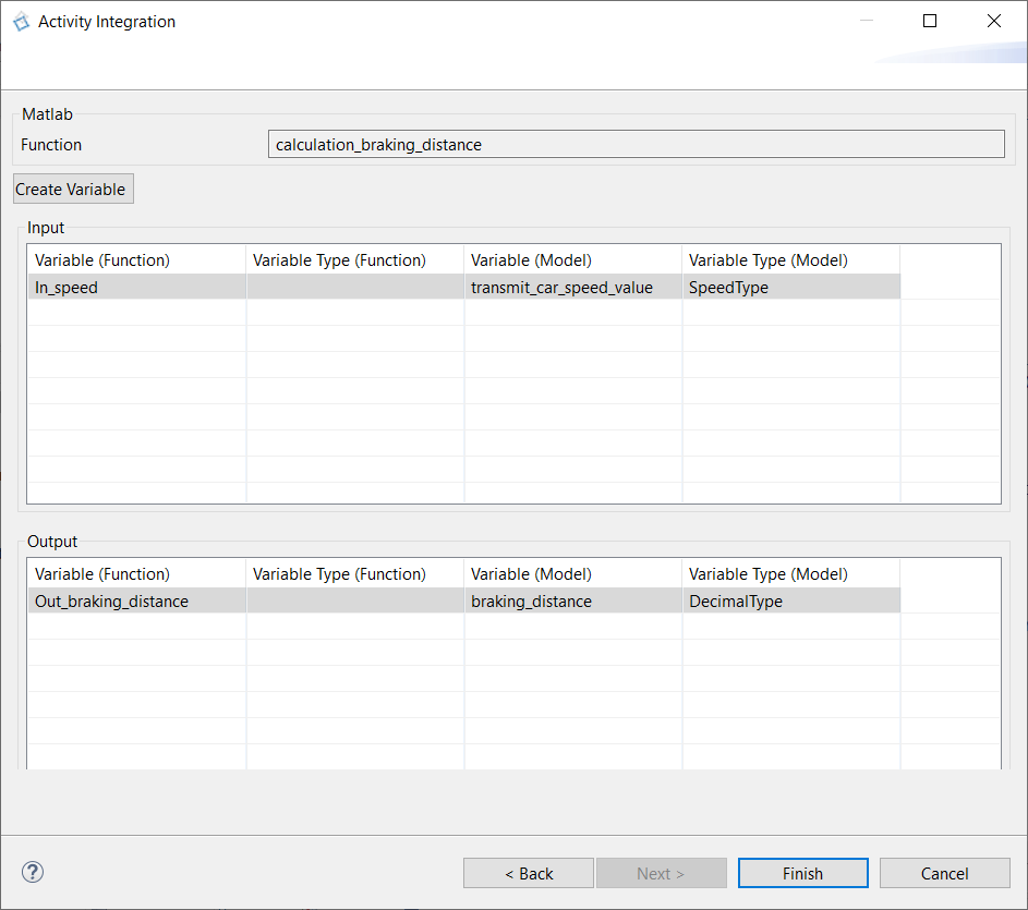
- Right click on the activity "determine_the_emergency_braking_status"
- Select Edit > Complete Activity > C++ Code
- Past the code below:
DecimalType minimum_distance;
DecimalType temp_distance;

if(an_obstacle_is_detected_value.RoadUsers.size()>0)
{
	minimum_distance = an_obstacle_is_detected_value.RoadUsers[0].dx1;
	for(unsigned int i=0; i<an_obstacle_is_detected_value.RoadUsers.size(); i++)
	{
		minimum_distance = std::min(minimum_distance, an_obstacle_is_detected_value.RoadUsers[i].dx1);
		minimum_distance = std::min(minimum_distance, an_obstacle_is_detected_value.RoadUsers[i].dx2);
		minimum_distance = std::min(minimum_distance, an_obstacle_is_detected_value.RoadUsers[i].dx3);
		minimum_distance = std::min(minimum_distance, an_obstacle_is_detected_value.RoadUsers[i].dx4);
	}


	if(minimum_distance < braking_distance*1.7)
	{
		emergency_braking_status  = ActivationType::activated;
	}
	else
	{
		emergency_braking_status = ActivationType::deactivated;
	}
}
else
{
	emergency_braking_status = ActivationType::deactivated;
}
If needed, this script will turn the variable emergency_braking_status to activated.
- Generate the state machine
USER STORY the_vehicle_brakes_automatically_in_case_of_emergency
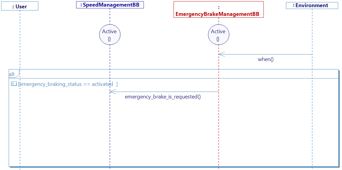
Remember, in the introduction, we told you that the EmergencyBrakeManagement service would not be in charge of affecting the speed in any way. We need to let the SpeedManagement service know that. For this, we will have to add a SpeedManagement lifeline in our diagram to which we will send the request to brake with emergency (only if the emergency_braking_status is activated).
- Add the SpeedManagement lifeline as done previously.
- Complete the user story with:
- A flow when from the Environment to our service that will allow us to have a trigger at each time step.
- A guard condition checking if the emergency_braking_status is activated.
- A flow between the two services lifelines to transmit the request to brake.
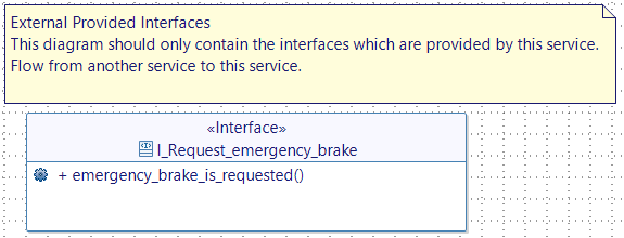
The diagram should look like this:
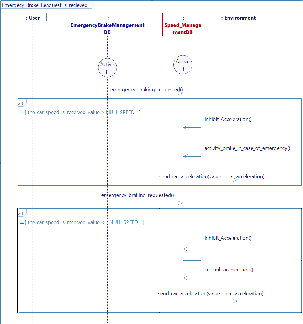
We now need to manage the reception of this request in the SpeedManagement service.
- Go into the SpeedManagement service.
- Create a new user story, especially for this case.
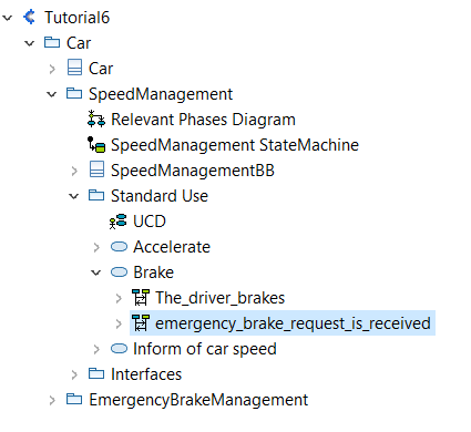
- Open the new user story
- Add the EmergencyBrakeManagement lifeline
- Add states for both of the services
- Recreate the emergency_brake_is_requested as a starting event for this diagram.
- Add a guard condition in which you will check if the speed is still positive.
- Create the internal activity inhibit_Acceleration, where the acceleration request is cancelled by setting the driver coefficient to zero.
This is added to prevent any acceleration while the emergency brake is active
the_driver_requests_to_accelerate_Coef = 0.0; - If it's the case, create the internal activity brake_in_case_of_emergency in which we will change the car_acceleration value, as done previously.
car_acceleration = -5.0; - Following the same way of sending back the acceleration to the simulation than before, trace the send_car_acceleration flow back to the environment.
- If we are in the case where the speed have reach 0, we need to create a guard condition for this, but this time using the set_null_acceleration internal activity used before.
- Generate the state machine
BUILDING PROJECT
- First, you need to check that you have generated the state machines of each (created or modified) diagram.
- Then generate the code (Overview > View Menu > Generate code).
If you have the community version of Designer (free version), please build the executable via Hub4Sys as shown on this page.
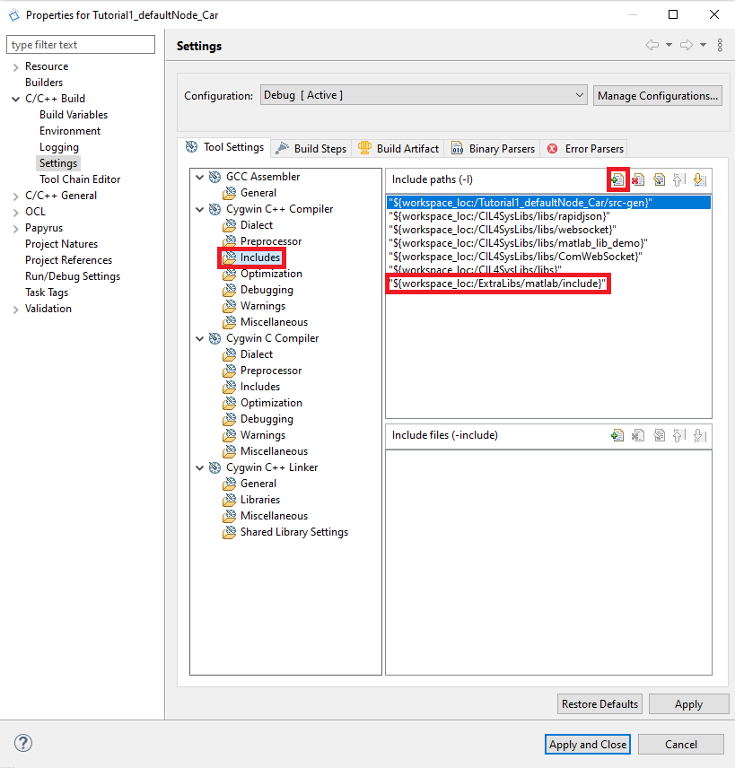
In order to build the project you will have to go into the properties of the generated code. In C/C++ Build > Settings:
- Go into Cygwin C++ Compiler > Includes.
- Add the path of the folder in which you can find your matlab .h. In our case, it is calculation_braking_distance.h that can be find in the folder ".../ExtraLibs/matlab/include"
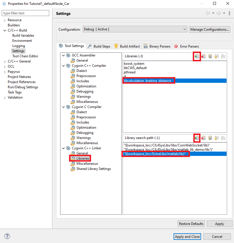
- Go into Cygwin C++ Linker > Libraries.
- Add the path of the folder in which you can find your matlab .a generated. In our case, the folder is ".../ExtraLibs/matlab/lib"
- Add the library name. In our case, it is called libcalculation_braking_distance.
SIMULATION MAPPING
-
Go on the Sim4Sys Virtual Bench: https://sim4sys.com/
-
You can reuse the scenario from first tutorial (if needed, you can follow the detailed steps from the Mapping part of Start to use Sim4Sys with a simple model (blackbox), to create a new scenario)
-
Update the XML file for the executable that you will use (see this paragraph)
-
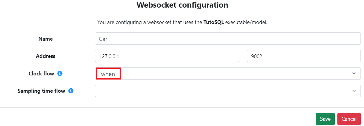
By right clicking on the websocket, you can configure the websocket
-
As a clock flow, select the when flow, it will then be sent every step.
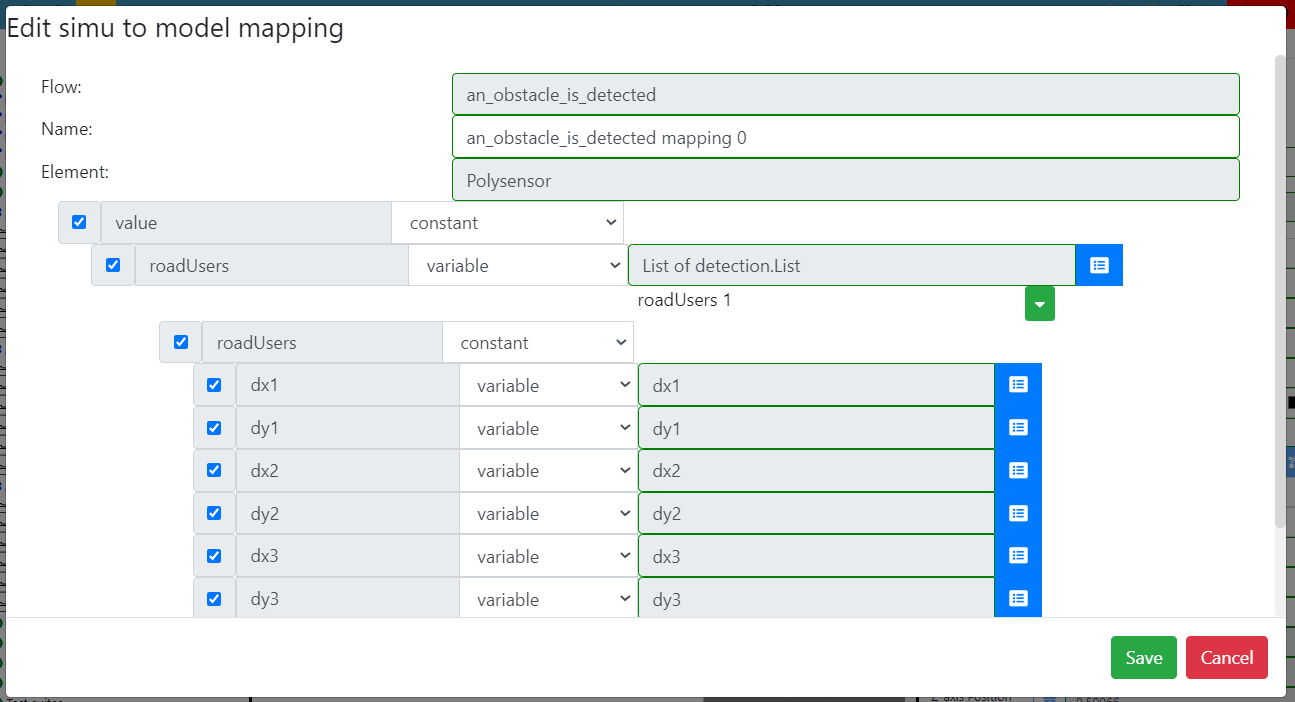
- Create a new simu to model mapping for the flow an_obstacle_is_detected_mapping :
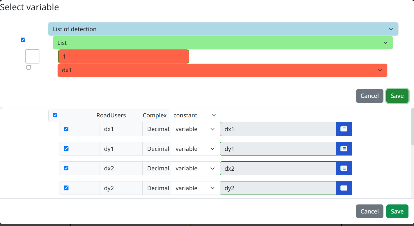
- Select variable after creating a new simu to model mapping (in this case, we have selected 'List of detection' related to the polysensor element)
-
In the scene2D context, Drag&Drop a polysensor element from the menu.
-
Attach the polysensor to the car :
- select both the car and the polysensor (by pressing Ctrl)
- right-click and choose "Attach"
-
Add the created simu to model mapping to the polysensor
-
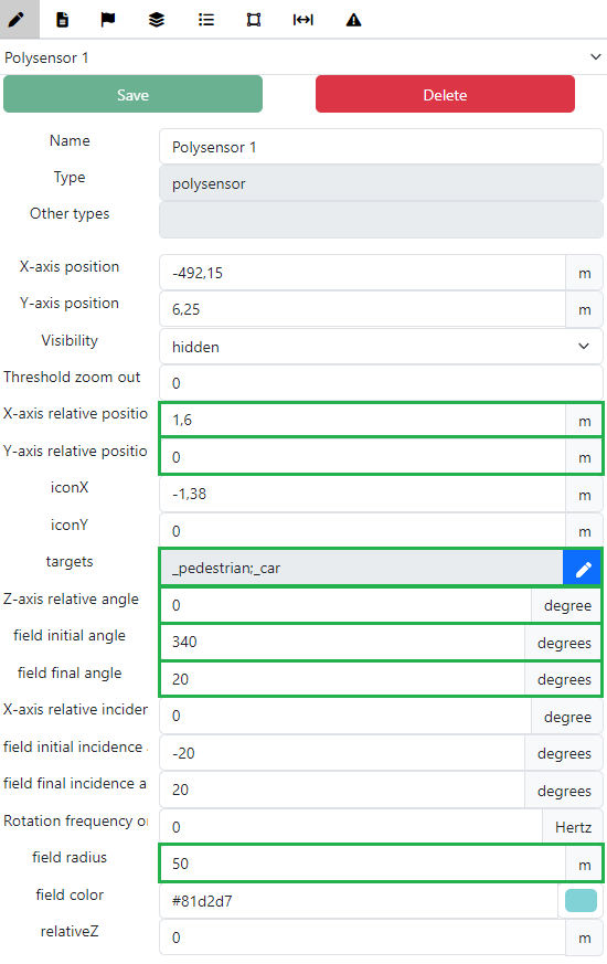
Modify the polysensor properties values as shown in green below (for example, the relativeX and relativeY coordinates depend on the position of the car) :
- Note that the polysensor field radius parameter value sets the maximum emergency braking distance, since obstacle detection is sensor-dependent.
-
To simulate an emergency braking case, we are going to add a pedestrian crossing the road.
-
Drag&Drop a pedestrian on the scene :
- The pedestrian must be placed in front of the car at the distance you want.
-
You can also add some decoratives elements in this context, like a road sign, a pedestrianCrossing element and roadPavement elements boarding the road, as you can see on this screenshot :

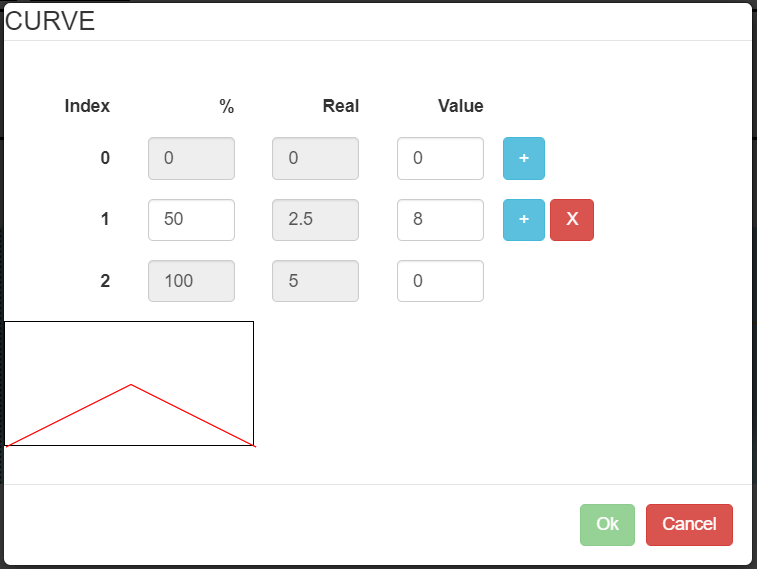
- In the timeline context, add an acceleration request whose value is set to a profile like this one:
- Add the acceleration Receive flow for the both elements.
Now the scenario is ready to play: you can connect the executable by clicking on the WebSocket button and click on play in Run mode.
The vehicle should brake automatically when the pedestrian is detected by the polysensor.
We can also note an area of amelioration. In our model, the user can still accelerate when the emergency brake is being activated. For this not to happen, we would need to have a priority system in our requests, where the emergency brake prevents all other requests to be taken into account. We can think of guard conditions for example.