Design the communication between two systems
PRESENTATION
The aim of this tutorial is to show you how to create a smart washing machine model. You will learn about model interactions, textual requirement generation and good practices proper to the processes of modelling.
Prerequisites
Have done the tutorial Include a matlab activity in a model.
News skills that you will acquire
On Designer:
- Link between User Stories,
- Concept on Inter System.
On Virtual Bench:
- Use a new Context elements: Hour display, SVG, ComboBox,
- Create model to model mappings,
- Use SVG in our library,
- Use multiple executables in a scenario, via our Launcher.
Duration
5h
INTRODUCTION
In this tutorial we are going to design a smart washing machine. The washing machine will have the possibility to be controlled from a Smart Device, which means the two systems will have to communicate with each other. To create our model, we will follow the same steps for each Use Case:
- Creation of the Use Case in Sim4Sys Designer: first the diagram which corresponds to the washing machine, then the one for the Smart Device (as communication between them is needed).
- Modeling of our Use Case by using Sim4Sys Virtual Bench: upload flows and creating the corresponding mapping.
- Requirement template generation: it is a good practice to generate our requirement template right after finishing every Use Case.
We will assume that you are already acquainted with some of the Sim4Sys Designer and Sim4Sys Virtual Bench procedures, but you will be able to check the documentation site to help you on the way.
WASHING MACHINE MODEL
[Sim4Sys Designer] Create the washing machine model
To start this tutorial you will have to create a new model.
- Create a new papyrus project model named "SmartWashingMachine". To do that, you can refer to New Model.
- Create a new projet "WashingMachine" (which will corresponds to the machine itself) (cf New Project)
- Create a service called "LaundryCleaning".(cf New Service)
- Create your Life Phase "Standard Use". (cf. Add a life phase to a service)
Create the states
Our washing machine will have two possible states: "On" and "Off".
Go to the LaundryCleaning StateMachine.
- Rename the FirstState to "Off". This will be the washing machine's initial state (when starting the simulation, the machine is turned off).
- Create a new state called "On". It will occur when the washing machine is turned on. Later in this tutorial you will create a second project called "SmartDevice" to allocate the elements of the device communicating with the washing machine.
[Sim4Sys Designer] Use case - Switch on
First of all, you will create the Use Case "Switch on" which allows you to shift the washing machine from the state "Off" to "On" at the user's request.
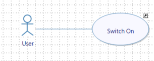
- Go to your LaundryCleaning service in the Life Phase Standard Use and click on Complete Use Cases (UCD).
- Drag&Drop an actor on the diagram and select User.
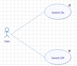
- Drag&Drop a new Use Case and name it "Switch On". You can create a link with the User if you want.
After following the previous steps, you should get a diagram of this nature:
[Sim4Sys Designer] USER STORY - The user switches on the washing machine.
In this Use Case the user will turn on the machine. When turning on, the washing machine should display useful information on its screen and activate a red pilot light.
- In LaundryCleaning service, more specifically inside the Life Phase Standard Use and the Use Case Switch On, create a User Story called "The user switches on the washing machine". (cf. how to create a User Story in a Use Case).
This User Story will have two Lifelines.
- Delete the one called Environment.
- Delete the Lifeline User.
- Drag&Drop the User lifeline with the stick figure symbol. This will be important for requirements generation.
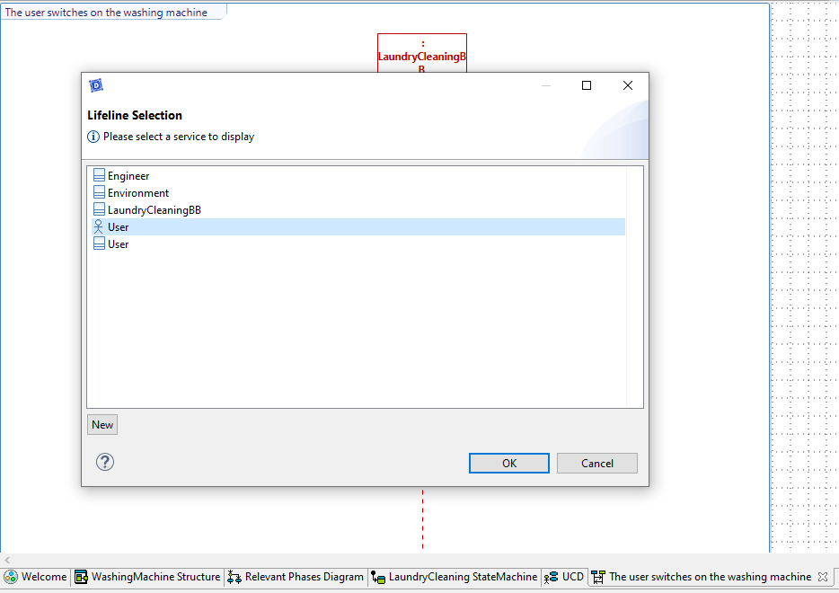
- Drag and drop the State Off on the service lifeline (cf. State)
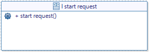
- Trace a flow between the user and "LaundryCleaning" and create your interface and flow as follows.
Go back to the Switch On user story.
- Retrace a flow between the User and your service, and select the flow you just created.
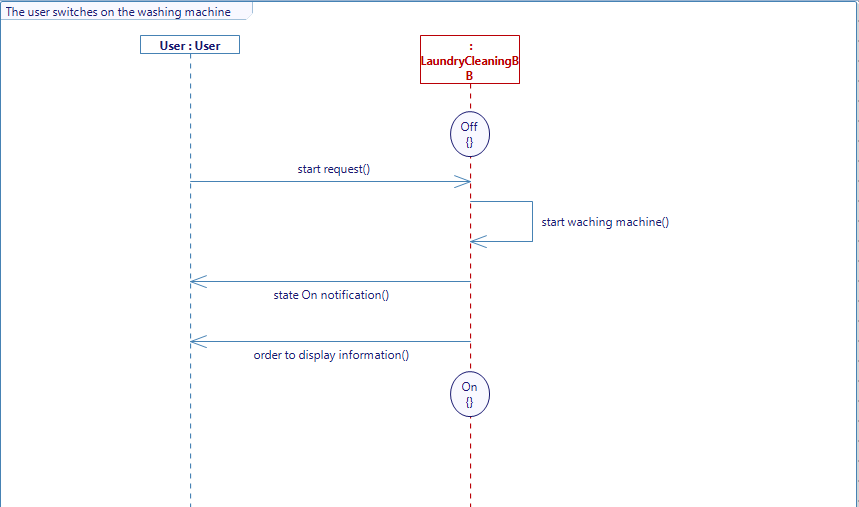
- Trace the rest of the flows and internal activities in order to get a diagram like the one below.
- Add the state On to the Lifeline LaundryCleaningBB. Don't forget to generate your diagram when it is complete.
- To generate the state machine right click on your diagram's background -> Edit -> Generate State Machines.
[Sim4Sys Designer] Use case - Switch off
You will now consider the case where the user turns off the washing machine.
- Go to your LaundryCleaning service in the Life Phase Standard Use and click on Complete Use Cases (UCD).
- Drag&Drop a new Use Case and name it "Switch Off". You can create a link with the User if you want.
After following the previous steps, you should get a diagram of this nature:
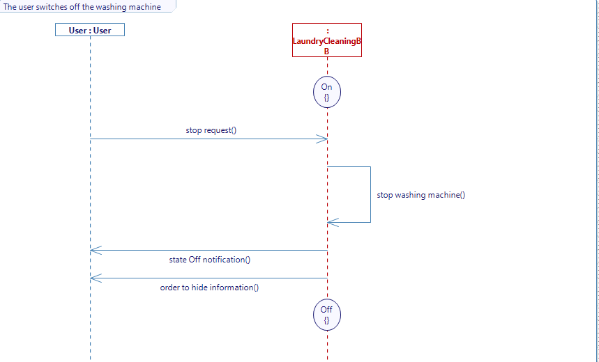
[Sim4Sys Designer] USER STORY - The user switches off the washing machine
-
In LaundryCleaning service, more specifically inside the Life Phase Standard Use and the Use Case Switch Off, create a User Story called "The user switches off the washing machine".
-
Do the same changes as before regarding the lifeline.
-
Trace the following diagram.
Don't forget to generate your diagram when it is complete.
[Sim4Sys Designer] Use case - Select program
Now that you are done with the change of states, you will manage the program selection on your washing machine. We will assume that there are two ways of controlling our machine: the order either comes directly from the user (the actor involved would be User) or the user controls the machine from his smart device (in that case the user is sending instructions but the actor would be the Smart Device.)
- Go to your LaundryCleaning service in the Life Phase Standard Use and click on Complete Use Cases (UCD).
- Drag&Drop a new Use Case and name it "Select Program". You can create a link with the User if you want.
- Drag&Drop an actor and select Environment
- Rename the environment actor to "Smart Device". You can also create a link betwenn your Use Case and the Environment.
After following the previous steps, you should get a diagram of this nature:
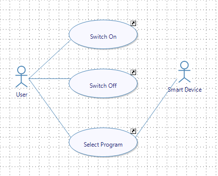
From this diagram, you translate the fact that there are two ways to communicate with the machine.
USER STORY - The user selects a program
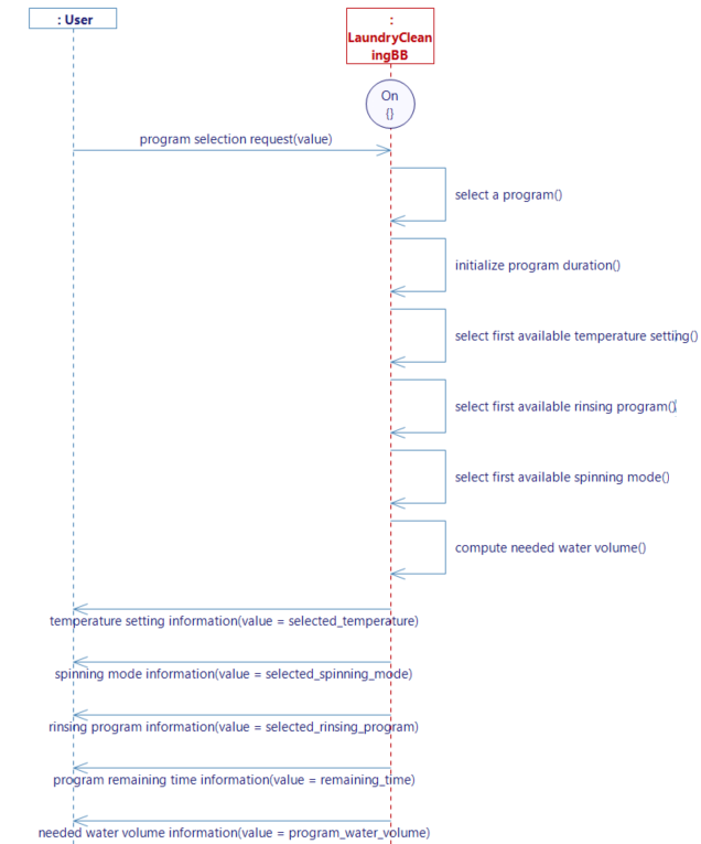
In this diagram the user will select a program directly on the machine. The washing machine will then select the desired program, set the program duration, choose the water volume needed, make a predefined temperature choice, choose rinsing program and choose the draining program. Those choices will be communicated to the user.
- In LaundryCleaning service, more specifically inside the Life Phase Standard Use and the Use Case Select Program, create a User Story called "The user selects a program directly on the machine".
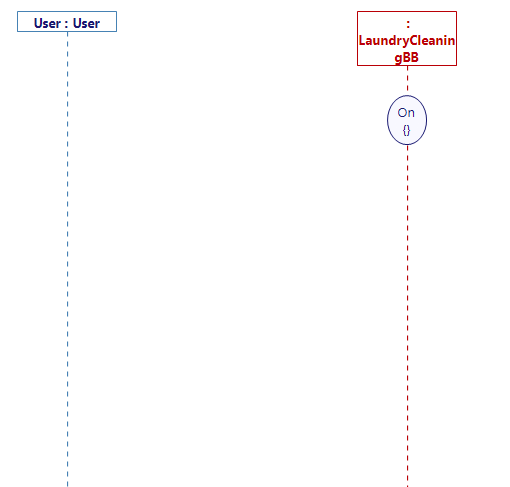
This User Story will have three Lifelines.
- Delete the Lifeline User.
- Drag&Drop the User lifeline with the stick figure symbol. This will be important for requirements generation.
- Delete the one called Environment.
- Drag&Drop the state On on your LaundryCleaning lifeline. The story occurs in the On state since the whole process takes place while the washing machine is turned on.
CREATE TYPE - ProgramKindType
Before creating the interfaces and flows, you have to define a new type (cf. Types). This type will be used to define the machine modes.
- In the Type diagram, add a New Enumeration and name it
ProgramKindType. - Drag&Drop eight Enumeration Literal inside of it:
Undefined,Cotton,Synthetic,Superfast,Eco,Sensitive,Rinsing_SpinningandDraining_Spinning
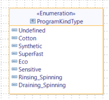
Back to the User Story - The user selects a program
- Trace a flow between the User and LaundryCleaning
- Create your interface and flow as follows.
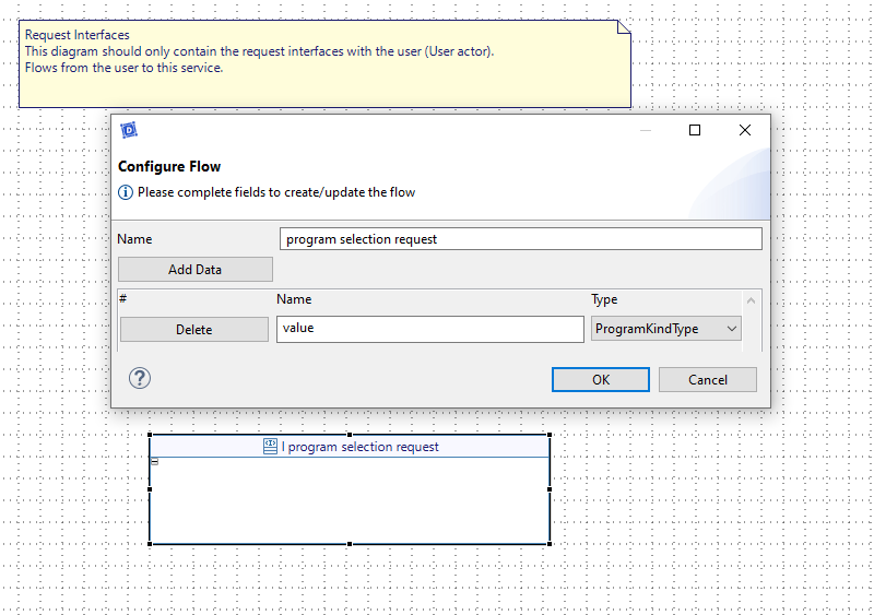
Do not forget to add a data named value to your flow and to assign to it the type you just created.
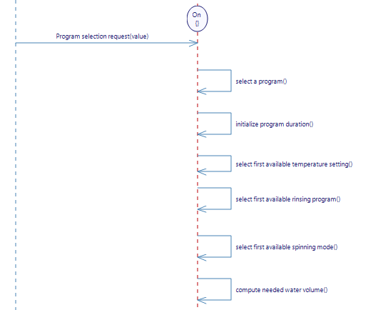
Back to the user story, create the following internal activities:
- "select a program"
- "initialize program duration"
- "select first available temperature setting"
- "select first available rinsing program"
- "select first available spinning mode"
- "compute needed water volume"
These activities are the different actions that will be completed by the washing machine every time the flow program selection request is sent. In other words, all those actions are triggered by the flow coming from the user that you just created.
CREATE TYPE - The washing machine parameters
Type - The washing machine different parameters values
Now that you have created all the internal activities, you also need to create new Enumerations for the different wash conditions :

These enumerations gather the different options offered to the user when it comes to temperature mode, spinning mode or rinsing program.
Type - Time
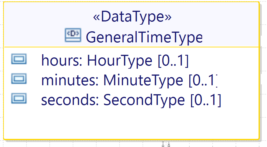
Create three Primitive Types with the Typedef IntegerType that will help define a DataType GeneralTimeType. Name them HourType, MinuteType and SecondType.
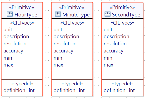
You can then create GeneralTimeType with three attributes of these types inside.
Do not forget to assign the types you just created to the attributes of the DataType, and to keep a multiplicity of "One".
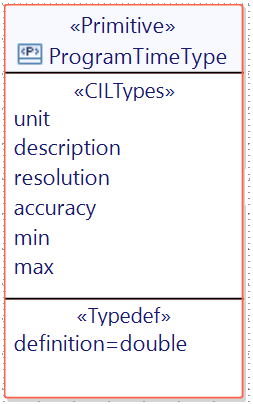
The user will also be able to start a program with delay start. You will then need a PrimitiveType of Typedef DECIMAL called ProgramTimeType.
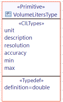
Type - Volume Liters Type
In order to quantify the water volume, you need to create a VolumeLitersType.
CREATE TYPE - The washing machine parameters
Create a new Enumeration called ProgramStateType with five Enumeration Literal :
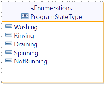
This type will signal the process ongoing in your washing machine.
Create a new DataType named ElementaryStepType :
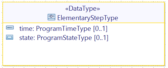
At this time it will be also necessary to create a new DataType, that you will call ProgramType, with its attributes :
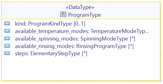
Each program can have mutliple temperature, spinning or rinsing modes available, which means you will have to define the multiplicity of the attributes to "Many" when you create them. The same goes for the attribute steps.
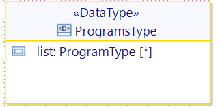
Now that you have the ProgramType, you can create the DataType ProgramsType which will contaiin a list of many programs. Don't forget to set the multiplicity of the attribute list to "Many".
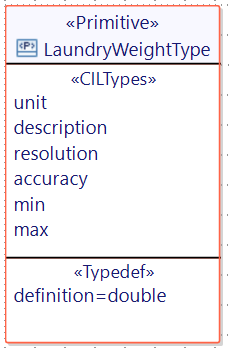
- Create a PrimitiveType called
LaundryWeightType
Back to the story The user selects a program
-
Create new variables by right clicking on LaundryCleaning lifeline -> Edit -> New variable. These variables will be
selected_temperature(TemperatureModeType),selected_spinning_mode(SpinningModeType),selected_rinsing_program"(RinsingProgramType),remaining_time(ProgramTimeType) andprogram_water_volume(VolumeLitersType). For each enumeration you can select the first literal enumeration as init value and for the decimal variables you can set the initial value to 0. -
Create a new variable in the lifeline "LaundryCleaning" called
loaded_laundryand assign to it "LaundryWeightType" with the initial value to 0. -
Create the remaining flows of the diagram below : for each flow add a value with the corresponding type (TemperatureModeType for Temperature setting information for instance) and when tracing the flow select the corresponding variable you previously created.
Sim4Sys Designer - Give behaviors to your activities
Before switching to Sim4Sys Virtual Bench, you have to complete the internal activities with the appropriate code. This code will define the behavior of your activity and therefore the behavior of your system during the simulation.
For your first internal activity (select a program) :
- Create a new variable in the lifeline LaundryCleaning called
selected_programand assign to it ProgramKindType. - Select your first internal activity -> Right click -> Edit -> Complete Activity -> Set Default Value.

This is a more simple way to retrieve a value and assign it to a variable. If you check the body of your activity after, you should see this :
selected_program = program_selection_request_value;
- Create a new variable in the lifeline LaundryCleaning called
recorded_programsand select the type ProgramsType.
Make sure that you have assign it to ProgramsType and not to ProgramType.
-
Select the second internal activity -> Right click -> Edit -> Edit body.
-
Copy paste the text below :
//Browse the list of recorded programs until you find the one you selected
//Add to remaining_time the duration of each step of the selected program
for (unsigned int i = 0 ; i < recorded_programs.list.size(); i++)
{
	if (recorded_programs.list[i].kind == selected_program)
	{
    	remaining_time = 0;
    	for (unsigned int j = 0 ; j < recorded_programs.list[i].steps.size(); j++)
    	{
        	remaining_time = remaining_time + recorded_programs.list[i].steps[j].time;
    	}
    	break;
	}
} -
Select the internal activity select first available temperature setting -> Right click -> Edit -> Edit body.
-
Copy paste the text below :
//Browse the list of recorded programs until you find the one you selected
//Set selected_temperature to the first temperature of the selected program
for (unsigned int i = 0 ; i < recorded_programs.list.size() ; i++)
{
    if (recorded_programs.list[i].kind == selected_program)
    {
        if (recorded_programs.list[i].available_temperature_modes.size() > 0)
        {
            selected_temperature = recorded_programs.list[i].available_temperature_modes[0];
        }
        break;
    }
} -
Select the internal activity select first available rinsing mode -> Right click -> Edit -> Edit body.
-
Copy paste the text below :
//Browse the list of recorded programs until you find the one you selected
//Set selected_rinsing_program to the first rinsing mode of the program
for (unsigned int i = 0 ; i < recorded_programs.list.size() ; i++)
{
    if (recorded_programs.list[i].kind == selected_program)
    {
	    if (recorded_programs.list[i].available_rinsing_modes.size() > 0)
	    {
		    selected_rinsing_program = recorded_programs.list[i].available_rinsing_modes[0];
	    }
	    break;
    }
} -
Select the internal activity select first available spinning mode -> Right click -> Edit -> Edit body.
-
Copy paste the text below :
//Browse the list of recorded programs until you find the one you selected
//Set selected_spinning_mode to the first spinning mode of the program
for (unsigned int i = 0 ; i < recorded_programs.list.size() ; i++)
{
    if (recorded_programs.list[i].kind == selected_program)
    {
	    if (recorded_programs.list[i].available_spinning_modes.size() > 0)
	    {
		    selected_spinning_mode = recorded_programs.list[i].available_spinning_modes[0];
	    }
	    break;
    }
} -
Select the internal activity compute needed water volume -> Right click -> Edit -> Edit body.
-
Copy paste the text below :
//Test the value of the variable selected_program with all the states in the enumeration ProgramKindType
//Depending on its value, program_water_volume will differ
//If selected_program does not match any of the state tested, program_water_volume is set to 0
switch(selected_program) {
    case ProgramKindType::Undefined :
	    program_water_volume = 0.0;
	    break;
    case ProgramKindType::Cotton :
	    program_water_volume = loaded_laundry * 8.0 + 20.0;
	    break;
    case ProgramKindType::Synthetic :
	    program_water_volume = loaded_laundry * 6.0 + 20.0;
	    break;
    case ProgramKindType::Superfast :
	    program_water_volume = loaded_laundry * 5.0 + 30.0;
	    break;
    case ProgramKindType::Eco :
	    program_water_volume = loaded_laundry * 3.0 + 20.0;
	    break;
    case ProgramKindType::Sensitive :
	    program_water_volume = loaded_laundry * 4.0 + 30.0;
	    break;
    case ProgramKindType::Rinsing_Spinning :
	    program_water_volume = loaded_laundry * 4.0 + 40.0;
	    break;
    case ProgramKindType::Draining_Spinning :
	    program_water_volume = 0.0;
	    break;

    default :
	    program_water_volume = 0.0;

}
Once all the activities are completed, don't forget to generate the State Machine. Now you can proceed with the code generation.
Sim4Sys Designer - Code generation
It is important to generate the state machine at the end of every use case you make. Make sure you have generated the state machine for the tree user stories you made (you can check the State Machine diagram). You can also generate your code and compile at the end of every use case you make if you want to target possible errors.
- In order to compile your projet click on the three dots near the Overview tab -> Generate and build.
- Chose to compile with Cygwin GCC. When your code successfully compiled, you can proceed to the next section. If not, use the console to spot the error in your model.
If you have the community version of Designer (free version), please build the executable via Hub4Sys as shown on this page.
[Sim4Sys VB] Create your scenario
In this part of the tutorial, we will broach the graphical simulation of the system.
- Open your Sandbox
- Create a new Scenario called "Washing Machine".
You have to create an HMI context. The HMI contexts are placed on the top left of your screen.
- To add one click on
 Scenario contexts.
 - Select the Type "HMI"
- Name it Operate washing machine (Live). Make sure to define it as main context (right-click on the context when you are not in Edit mode).
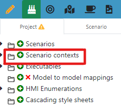
You can Show/Hide some of your contexts by right-clicking on them. The configuration of the contexts can be different for every scenario.
[Sim4Sys VB] Create the graphical elements
Create the washing machine SVG
First you have to place your washing machine in that HMI context by adding some SVG images. Those SVG images are provided by the SVG library in Virtual Bench.
In SVG library -> Edit SVG you will find the different pictures that will compose your washing machine:
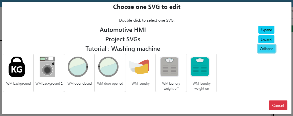
Create the first component - WM background
- On your Scenario HMI context drag and drop an SVG image element to your scenario. If it does not appear in the available elements you have to go to your context configuration and select the element "Svg image".
To move an object that's already on the HMI context, select the object then press Alt while moving it.
- Name it "WM background".
You will just see an SVG image text, but you can select the svg that you want from the library. To do so :
- Click on the second button next to the SVG Def of the SVG image element you just added (see picture below).
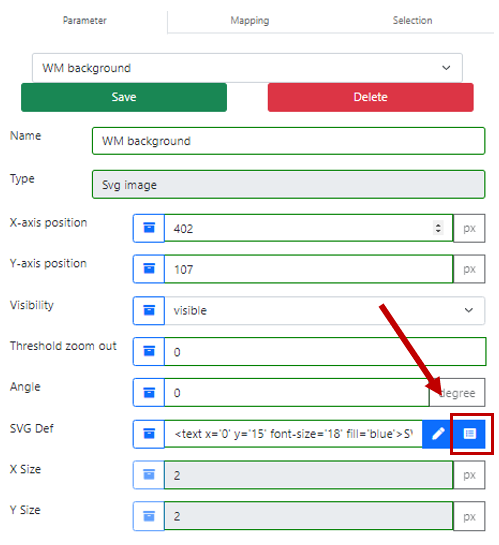
- Double-click on the image WM background 2
- Save the modification on the element
Do not forget to click on "Save" every time you make a change in the parameters.
You should obtain this result:
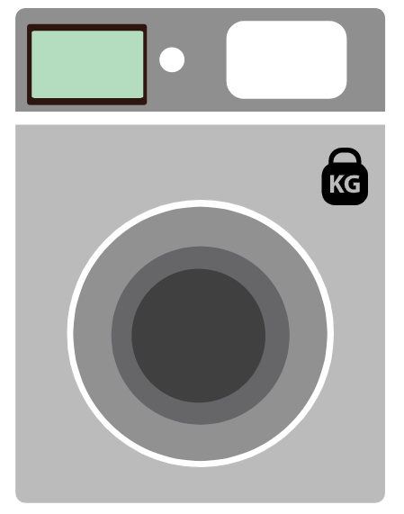
You are now ready to continue with the mapping.
[Sim4Sys VB] Create your Websocket
Before anything else, you need to create an executable and join it to your scenario.
-
In the tab Scenario, create an executable in the Project tab by clicking on
 next to Executables and name it "Washing machine"
 -
Go back to Sim4Sys Designer and click on your "WashingMachine" project (Overview -> Service) and then click on Export file XML. (more informations here)
-
On Virtual Bench import the xml file on your executable. 6 types and 12 flows should be created. Now you are ready to start with the mappings. (more informations here)
-
Add the path to your executable (that you compiled before) in Virtual Bench to make the connection to Sim4Sys Designer possible.
-
Add a websocket in the scenario tab and name it "washingmachine" to allow the connection with Sim4Sys Designer.
[Sim4Sys VB] Add the mapping of the User Story The user selects a program
In this section you will create mappings, which define the links between Sim4Sys Designer and our Virtual Bench simulation. You will start with the flow allowing you to select a program. As you have seen when you created the ProgramKindType, there are eight different programs which will constitute eight enumeration values.
Washing program selection
Create the enumeration
To select a program you will use the commodo element. To define a new enumeration for your commodo button, you will have to create a new HMI enumeration with the different programs available in the washing machine.
-
Click on
 next to HMI Enumerations. You will find it in the "Project" tab, on the right side of the screen.
 -
Add the states
Undefined,Cotton,Synthetic,SuperFast,Eco,Sensitive,Rinsing SpinningandDraining Spinning. By default you will have an icon for each state. Change the definition to have a text instead of an icon. All definitions should look like this :<text x='0' y='30' fill="black">Undefined</text>
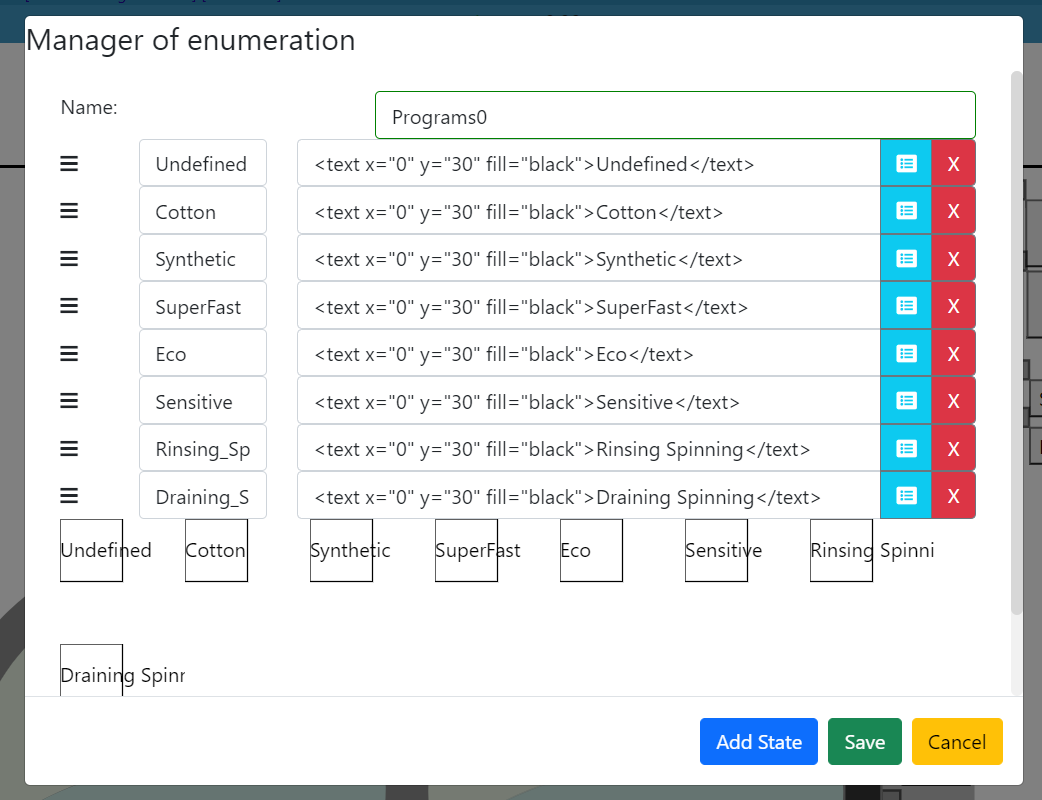
- Add a Commodo button to the left of the washing machine SVG. Name it "Program selection". In State parameter of your object you can select the enumeration you just created.
Create the mappings
Now you will create the simu to model mapping for this object.
- Right click on the commodo object -> Simu to model mapping -> Create model to simu mapping
- In the Type field, choose Enumeration and then the state you want to be associate to the simu to model mapping

- In the next pop up, do not forget to tick the box "value" and choose the right enumeration.
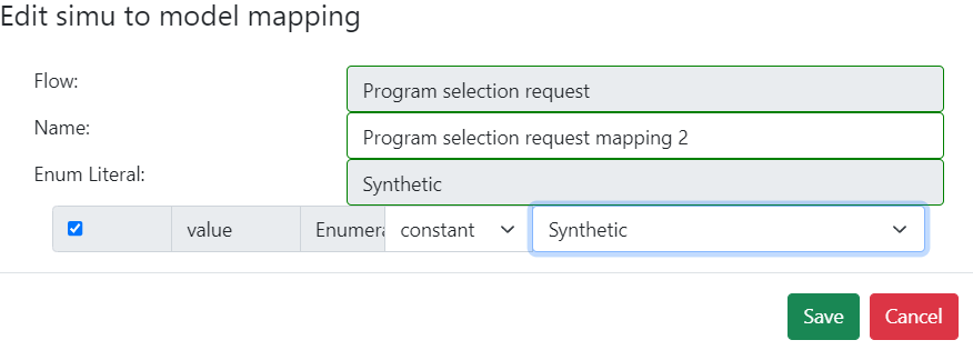
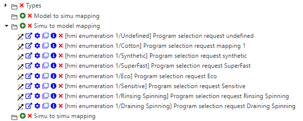
Do the same thing for each program enumeration. You should have 8 mappings on the element commodo.
Feedback to the user
To continue, you will create the mappings for the feedback flows (from the service to the user). Temperature setting information, spinning mode information and rinsing program information will be displayed on the left side of the machine's white screen.
- Add three text objects in the white screen. You can change the name of each element and the text parmater as below.
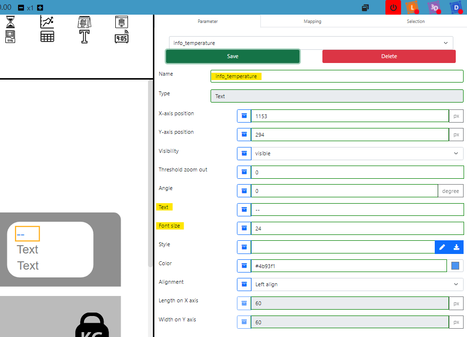
Temperature setting informations
On the text with temperature information :
- Create a new model to simu mapping and select the flow temperature setting information. You will add a mapping for each temperature available.
- Name it "temperature setting information 20".
- In the Element Fields tick the box Text and write
20°C. - Click on Add parameter condition and select Temp Cold 20. This will make the previous text appear only if Temp Cold 20 is selected by the user.
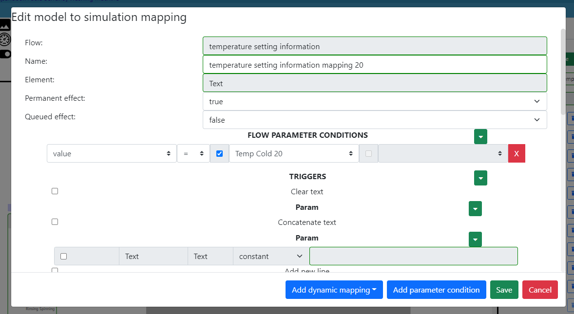
- Repeat the same procedure for Temp 30, Temp 40, Temp 60, Temp 90 et Temp NA.
Rinsing program information
- In the second text object, create a model to simu mapping selecting the flow rinsing program information. Create a mapping for each mode following this example :
- Tick the box text and write "Mode 1"
- Add a parameter condition and select One.
- Repeat the same procedure for Modes 2, 3, 4, 5 and NA.
Spinning program information
- In the third text object, create another model to simu mapping selecting the flow spinning program information. Create a mapping for each mode following this example :
- Tick the box text and write "0 rpm"
- Add a parameter condition and select Spinning 0.
- Repeat the same procedure for Spinning 400, 800, 1000, 1200 and 1400.
Program remaining time information
- Add an Hour display object on the the green screen. You can change the color of the text to black to make it more visible.
- Change the Mode of the object to Only seconds.
- Create a model to simu mapping and select the flow program remaining time information.
- Check the last Seconds box in Element Fields and change from constant to variable.
- Choose the parameter value by clicking on the blue button.
- Save the mapping.

Needed water volume information
- Add a Number object at the bottom right of the green screen.
- Change the field Precision to 1.
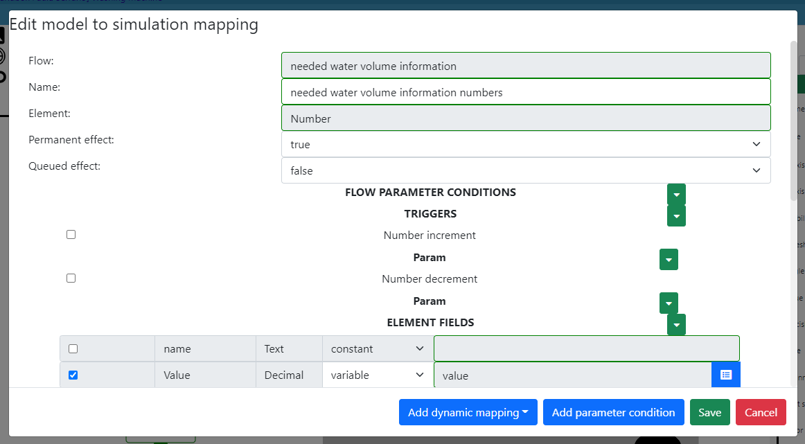
- Create a Model to simu mapping and select the flow needed water volume information.
- Tick the box Value and change from constant to variable.
- Choose the parameter value.
- Save the mapping.
[Sim4Sys VB] Mapping of the User Stories The user switches on the washing machine and The user switches off the washing machine
You have already finished the mapping for the diagram The user selects a program . Now let's deal with the two other user stories.
Start information picto generic
In order to inform the user of the washing machine's state (on or off), you will use a Picto generic. It will have two different positions : On and Off. According to its state, the icon will change. To create this pilot light, you will add a new HMI enumeration. You can find all your HMI enumerations -as well as the possibility to create one- in the tab Project.
-
Create a new HMI enumeration and name it OnOffLed.
-
Add a state Off and select the svg called State Off. To select an svg from the library click on the blue button next to the definition.
-
Add a state On and select the svg called State On.
-
Add a Picto generic element in the center of your washing machine's top.
-
Change the Enumeration literal field
 to choose OnOffLed. You may have to move the object again to place it where you want.
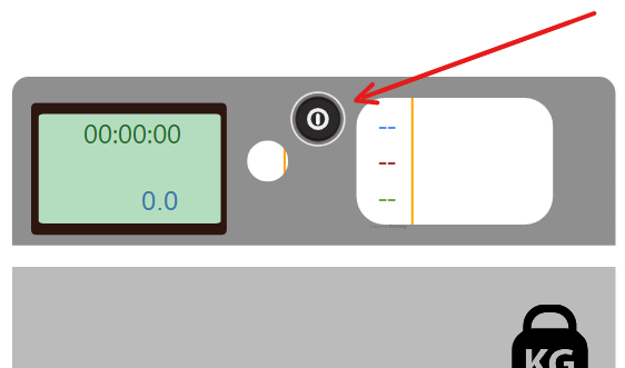
- Add two buttons to the right of the washing machine and name them Switch On and a Switch Off. The name of the element and the text appearing on the button (buttonLabel) are two different parameters.
You can change the style of the button by changing the style parameter using CSS, but this is for aesthetic purpose only (see for exemple :https://www.w3schools.com/css/css3_buttons.asp).
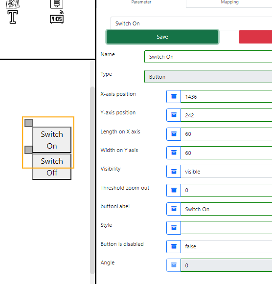
Now that you have all the needed graphic elements, you will have to add the mappings for both user stories.
Start request
- On the Switch On button, create a simu to model mapping for the flow start request.

- On the picto generic, create a model to simu mapping for the flow state On notification.
- In the second pop-up, change the field Enumeration literal to On. Make sure to choose the right enumeration to find the state On.
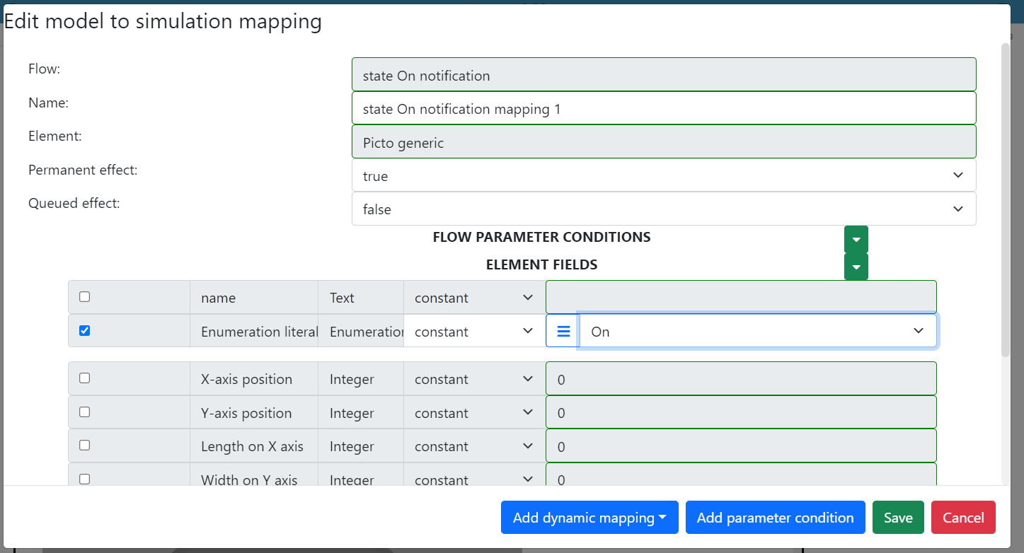
Stop request button
-
On the Switch Off button, create a simu to model mapping for the flow stop request.
-
On the picto generic, create a model to simu mapping for the flow state Off notification.
-
In the second pop-up, change the field Enumeration literal to Off.
Change the visibility of the information
- Drag&drop a text object which will mark the water's volume display. Place it above the number with water's volume.
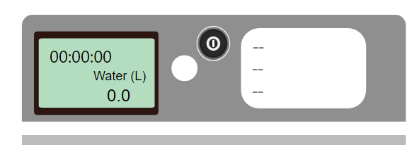
- Change some of the fields of the object as follow:
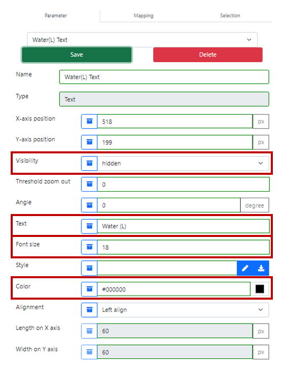
Display information
For the three objects on the green screen (Hour Display, Text and Number):
- Create a model to simu mapping for the flow order to display information.
- Check the box Visibility set on Visible.
- Save the mapping.
Hide information
For the three objects on the green screen (Hour Display, Text and Number):
- Create the model to simu mapping for the flow order to hide information.
- Check the box Visibility set on Hidden.
The two mappings on each object will allow to hide or display the element according to the flow sent by the model. Make sure in the parameters of the three objects on the screen that the Visibility parameter in on hidden. When you start your simulation there should be nothing visible on the screen (the machine is turned off).
Sim4Sys Virtual Bench - Test your simulation
Open the file explorer and find the executable of your washing machine (if you compiled you model, you can find it in Washing_Machine_defaultNode_WashingMachine -> Debug).
- Open your executable file. You may need authorization if it is the first time you are running it.
- Go back to Sim4Sys Virtual Bench. Click on the websocket button.
 It should switch from red to green. That means your websocket is correctly connected and you can start the simulation.
 - Click on the play button to start your simulation. You can play with the buttons you created and check that the user stories you created are working :
- Press the Switch On button to see your washing machine turning on. There should be a display on the screen and the button should turn red.
- Select a program with the commodo. Information on the white screen should appear. When switching from a program to another, the water volume should also change.
- Press the Switch Off button to see your washing machine turning off. The display on the green screen should disappear and the button should turn grey.
These are the three user stories you created in your model. If everything worked as it should, good job ! You can now generate the requirements of your model.
[Sim4Sys Designer] Generate the requirements and check them
When the behavior of your system is approved, you can generate the requirements related to your use cases.
- Click on Service tab included in Overview.
- Select the folder "LaundryCleaning" and Generate Requirements. A pop-up will appear to ask you to choose a template.
- Select the checkbox All available Requirement Templates.
- Select CIL_02 - Inline English Generic Template.
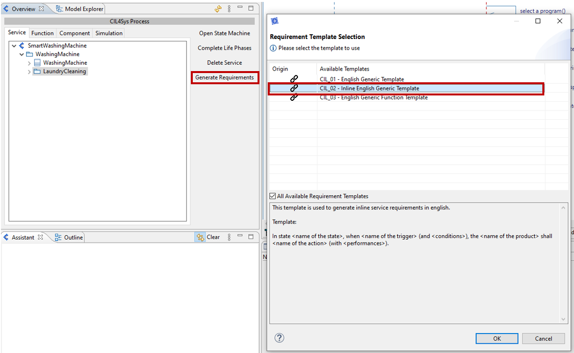
You can see each requirement by going in the Overview and clicking on User story -> Internal -> REQ-LaundryCleaning-... and opening the tab Properties.
For the first user story the requirement should look like that :
In state Off when start request is received, the system WashingMachine shall : start washing machine,send state On notification, send order to display information and switch to state On.
The requirement is generated automatically with all the elements on your diagram. If the requirement does not make sense, you can change the elements on the diagram that seem to be probelmatic (the name of a flow, state or variable). Generating the requirement is a good way to check if your diagram is done properly. Therefore it is a good practice to generate and check the requirements as you are modelling your system. Keep in mind that the requirements of a system are as important as a good simulation when it comes to modelling.
SMART DEVICE COMMUNICATION
So far, we have worked with just one part of the system : the washing machine. It is now time to add the smart device part. As you can remember, there will be two ways of controlling the machine : the user can directly send an order with the buttons, or the user can send an order through a smart device. In the first case, the machine will send feedbacks to the user directly (through the screens on the washing machine), but in the second case the machine will send feedbacks to the user AND to the smart device (we can imagine that the person using the smart device is not in front of the washing machine but still needs to know what is happening).
[Sim4Sys Designer] Create the user story The system receives a request to select a program
You will now create a user story where the program selection request will come from the Smart Device.
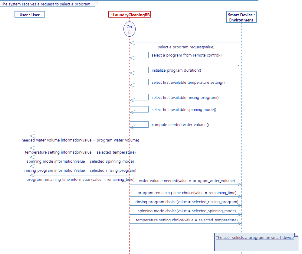
- Create a new diagram in the Use Case Select Program and name it "The system receives a request to select a program".
- Delete the lifelines User and Environment.
- Drag and Drop the lifelines User (the one with the stick figure symbol) and Smart Device.
- Create the flows and activities to match the diagram below. Note that some of the elements were already used in the previous user story, so you can just reuse them.
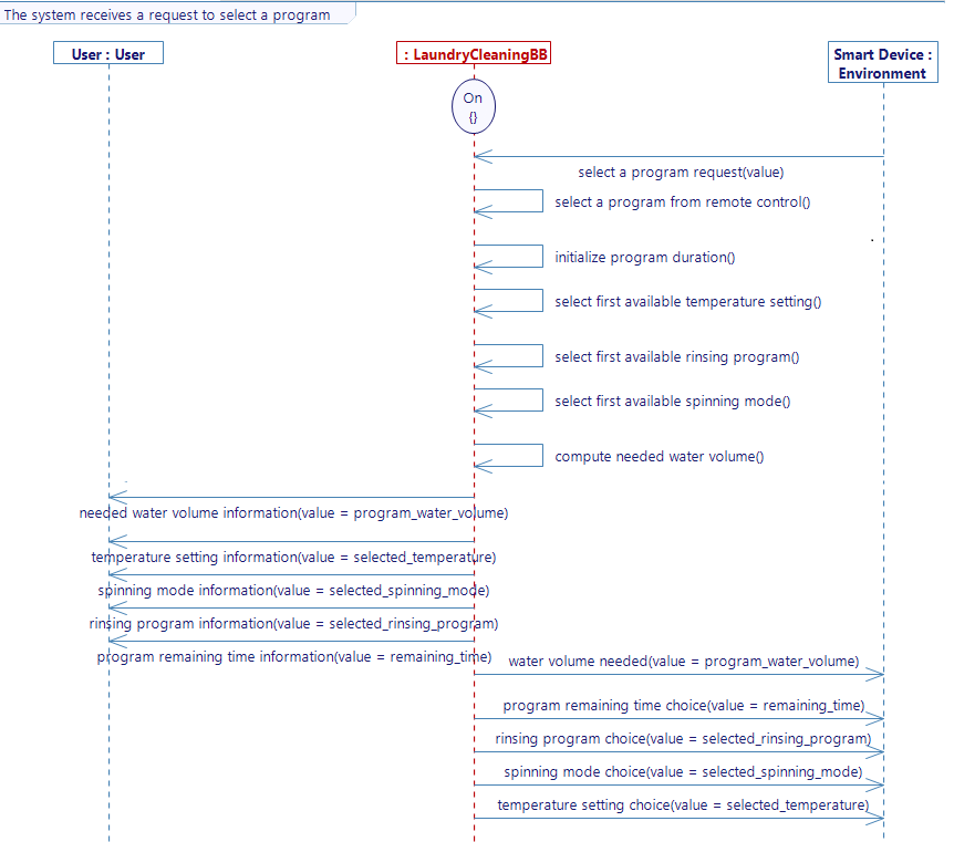
The new feedback flows you will have to create are shown on the picture below :
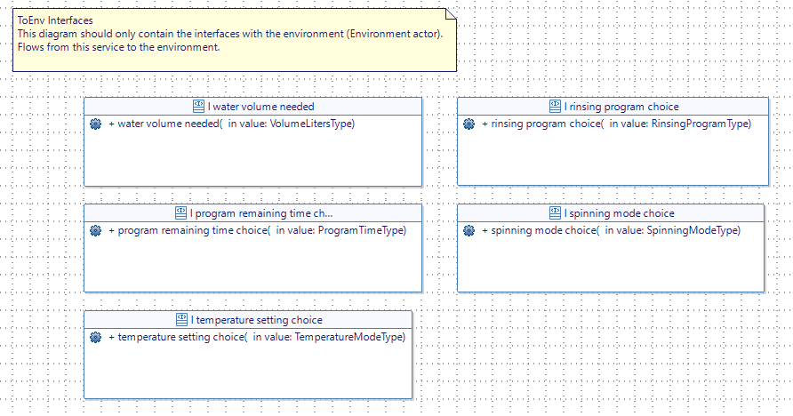
All the activities you reused are already completed.
- Complete the first activity to retrieve the value coming from the flow select a program request and to store it in the variable selected_program. The body of your activity should look like that :
selected_program = select_a_program_request_value;
- Generate the state machine when the diagram is complete.
- Generate the requirements again and check that it makes sense.
If you change the flows in your model you have to export your XML file again and update it on Virtual Bench. Do not forget to generate and build the code to update the executable.
[Sim4Sys Designer] Create the smart device model
- Create a new project (like "WashingMachine") and name it "SmartDevice"
- Create a New Service, name it "WashingMachineControl".
- Add Standard Use Life Phase.
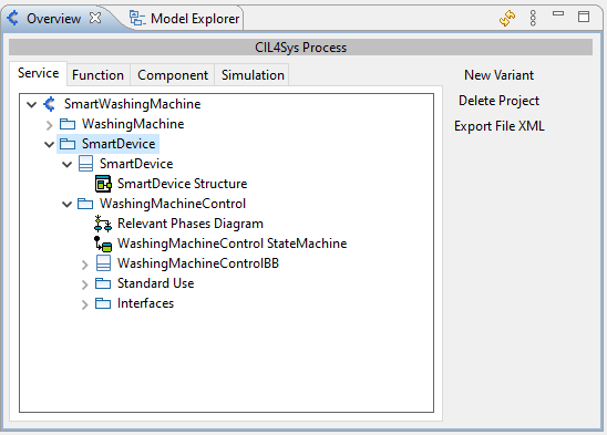
[Sim4Sys Designer] Create Use case - Select program
- Complete the use cases diagram as you see in the image below.

[Sim4Sys Designer] USER STORY - The user selects a program on smart device
-
In the use case you just created, create a user story: "The user selects a program on smart device".
-
Replace the lifelines User and Environment respectively by User (the one that you added in your User Story) and WashingMachine.
-
On the State machine diagram rename the state FirstState to "Active" and on the user story add it to your lifeline WashingMachineControl.
-
Complete your diagram as the one below. All the flows have a parameter with the type ProgramKindType.
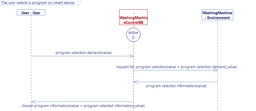
You can notice that this diagram actually includes two user stories : the user sends a request and the washing machine sends a feedback. It would have been more appropriate to separate them but for reasons of usability for this tutorial we keep it like that.
[Sim4Sys Designer] Create the communications between the two models
With this diagram alone, there is no way to know that this user story is linked to another one. This can be a problem if many people work on the same project. To address the lack, you can add a reference in your diagram that will redirect you to the other one.
Complete the user story The user selects a program on smart device
- Drag&Drop a Diagram Reference in order to create the link to The system receives a request to select a program. If you double-click on the reference you will be redirected to The system receives a request to select a program story.
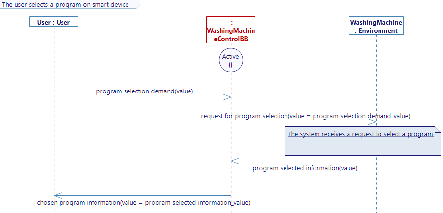
After finishing your User Story, do not forget to generate the state machine, generate the code of the project SmartDevice and to build the code. A new file named "Washing_Machine_defaultNode_SmartDevice" is created with the executable corresponding to your Smart Device.
Complete the user story The system receives a request to select a program you have created in the WashingMaching project
A reference goes both ways : if you made a reference in one diagram to another, do not forget to make it in the other diagram to redirect to te first one.
- Drag&Drop a Diagram Reference in the story The system receives a request to select a program in order to create the reference to The user selects a program on smart device
[Sim4Sys VB] Add a second Websocket
The smart device being a different project on Designer, you have to create a new executable in your VB project. Name it "Smart Device". Then create a new websocket in your scenario for this new executable.
When you create a new executable :
- Do not forget to import XML file to make the mappings.
- Do not forget to add the path to your executable. Now that you have two executables you will use the launcher to connect to both at the same time.
[Sim4Sys VB] Create the graphical elements
To continue, you have to create the hmi of the smart device. The final result should look like the picture below.
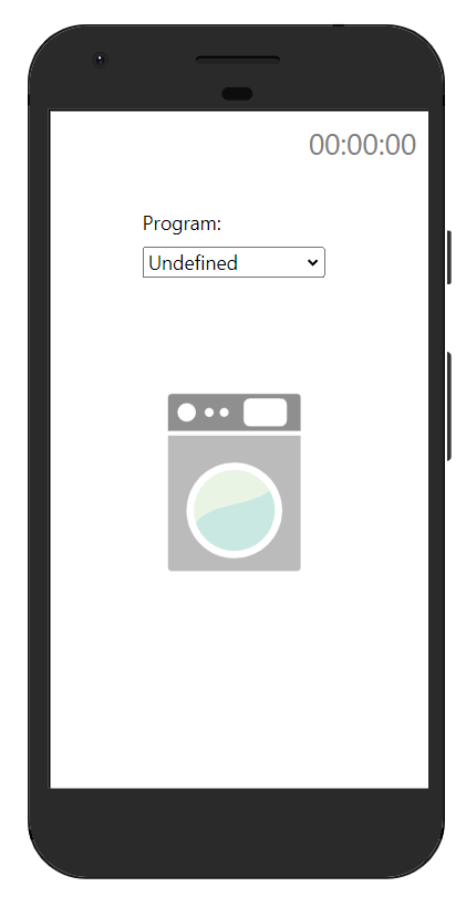
To do so :
-
Create a new context HMI. In the configuration of a context you can change the icon for the context. This will help you distinguish contexts in your project.
-
Add the object Hour display, rename it "GeneralTimeDisplay" and change the mode to "Only seconds".
-
Add two SVG objects : one for the phone and one for the icon of the washing machine. You can find both in the SVG library.
-
To allow the user to select the program, add a Combobox object in the top of the screen of your smart device. You can call it "Select a program".
-
Choose Programs in the field Enumeration literal and "Program" in the field Label.
[Sim4Sys Designer] Mapping the flows
Mapping the combobox
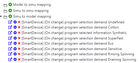
- Create a simu to model mapping for the flow program selection demand for each enumeration value (eight in total). Make sure to choose the right executable to find your flow.
When you are done you should have these mappings :
Mapping the communication between the Smart Device and the Washing machine
If you want the two models to communicate you still have to describe this communication. In this case, you want a flow from one model to be sent to another model, hence the usefullness of the model to model mappings.
- In the tab Project, create a model to model mapping linking the flow [SmartDevice] request for program selection to the flow [Washing Machine]select a program request.
- Change the value enumeration into variable. You will obtain the following mapping.

- Add this model to model mapping instance to your scenario (go to the Scenario tab and you will be able to add existing model to model mappings).
[Sim4Sys VB] Test your simulation
When you have more than one executable, the launcher comes in handy. You can download it by clicking on Help and Download. Once it is downloaded :
- Open the launcher and click on Start Launcher.
- On Virtual Bench, click on the Launcher icon in the top right corner. The button should turn green. If you have filled the right path for both executables (on the Project tab), both should open. Everytime you click on the stop button the executables will close and open again.
- Start the simulation.
- Open the HMI context with the smart device. Every context opens in a separate window.
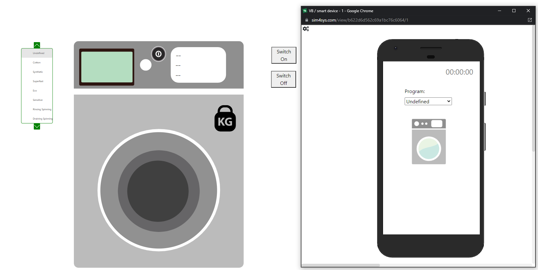
- In the machine context, switch on the machine with the button.
- In the smart device context, choose a program from the smart device. The information about the program should appear on your washing machine's screen and the water volume should be updated.
[Sim4Sys Designer] Generate the requirements and check them
Just as we did for the washing machine model, you can generate the requirements for you smart device model.
- Click on Service tab included in Overview.
- Select the folder WashingMachineControl and click on Generate Requirements.
- A pop-up will appear to ask you to choose a template.
- Select CIL_02 - Inline English Generic Template.
Go further
This tutorial gives you an idea of what is possible in a model. You could elaborate your model with other user stories and add more complex behaviors. Here are a few examples of use cases you can add :
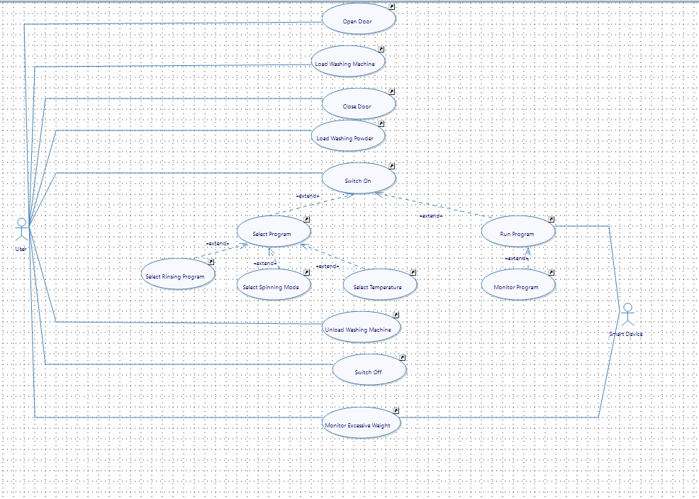
You can also use the available svg in the library to complete both HMI with any new feature.
Get creative !