Visualize using a sequence diagram
Presentation
This tutorial focuses on using the sequence diagram object in Virtual Bench to visualize dynamic system interactions. At its core, this virtual bench element represents lifelines, where flows appear dynamically during the visualization. In this tutorial, we will focus on the specific usage of the sequence diagram to represent the inter-system connections between models that the user has previously created. For this, we will go through the example of a Heating System.
Preparing the Models in Papyrus Designer
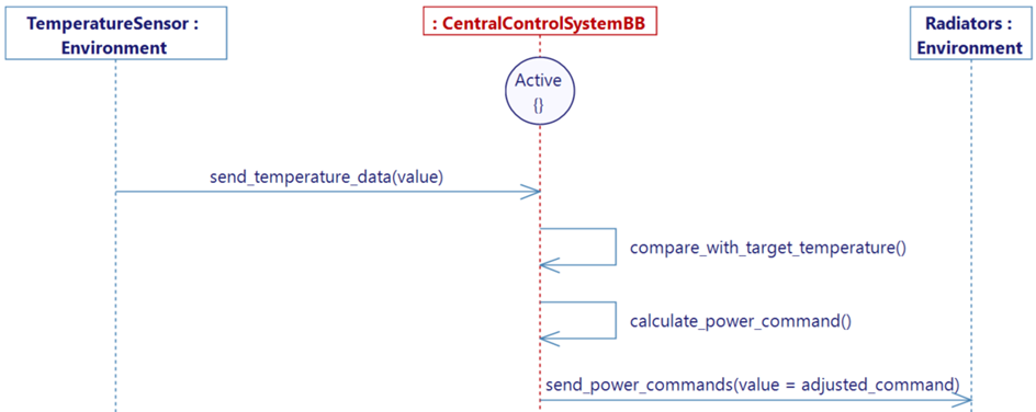
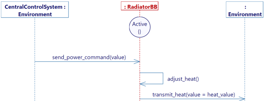
First, the user must have designed several models within Papyrus Designer. Each model will correspond to a lifeline in the visualized sequence diagram. The Heating System is divided into the following models:
- A Temperature Sensor, for the System to understand its Environment in order to adjust the system.
- A Central Control System, to receive data, make decisions, and control the System.
- A Radiator, connected to the Central Control System, receiving the orders, and producing heat. It is possible to instantiate the Radiator several times for the visualization. This means that the Central Control System may communicate to more than one Radiator.
Here is an example of the set of models you can aim for in this tutorial.

Creating a Visualization in Virtual Bench
Preparing the visualization
When your models are ready, generate each executable and export each .xml file. You can now transition to the visualization in Virtual Bench.
Configuring the new executables in Virtual Bench
Follow these steps to properly configure the new executables in Virtual Bench.
Step 1: Create new executables
Open Virtual Bench and, for each model, create a new executable:
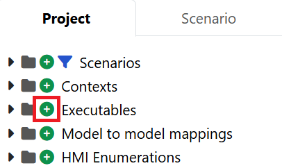
- Name the new executable (e.g. Radiator), and specify the path to the
.exefile you previously generated from your model (in order to use the launcher). - Import the previously generated XML file (Here Radiator.xml).
Step 2: Complete Flow Configurations
-
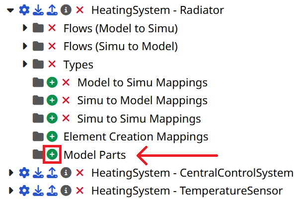
Create the Model Parts.
We will have to create Model Parts manually. A Model Part is what will allow the sequence diagram to understand what should be treated as a lifeline.
-
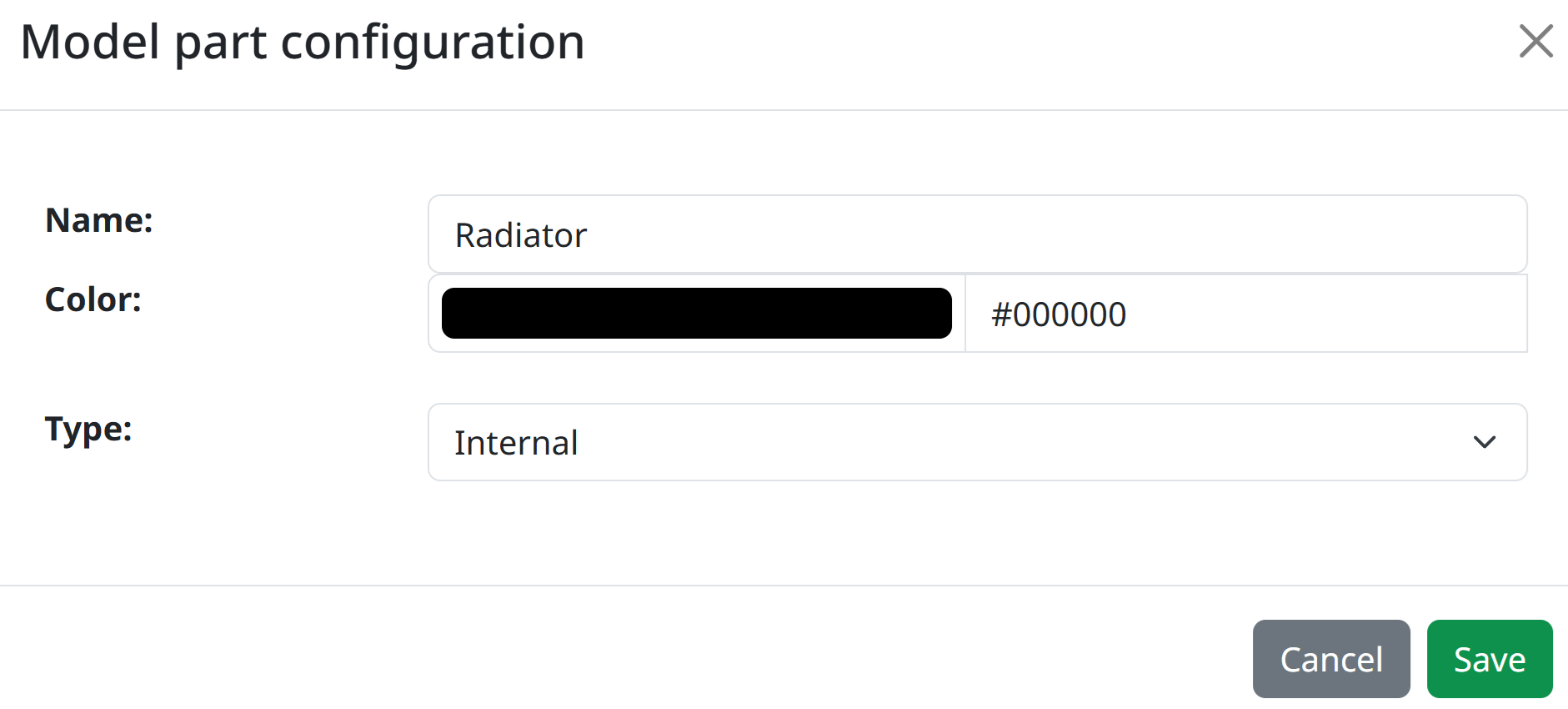
For each model (therefore, for each executable in Virtual Bench), add an internal Model Part of the system defined by the executable. (e.g. A radiator internal model part in the Radiator executable.)
-
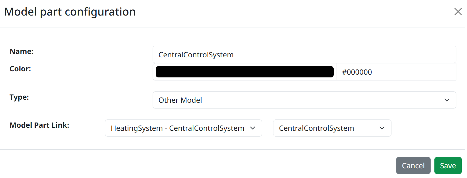
Only after creating all necessary internal Model Parts in every executable, add a Model Part for every system each executable interacts with. (e.g. A CentralControlSystem model part in the Radiator executable.). Choose the Other Model type and select the correct Model Part Link, in the referenced executable.
-
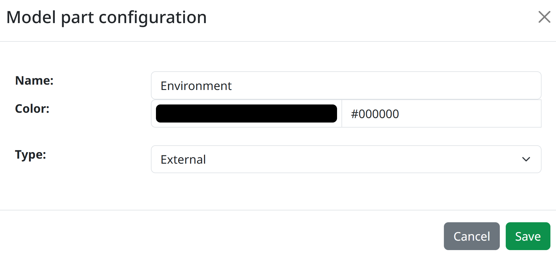
Also add external model parts in case you have external actors that are not another executable. (e.g. The Environment model part in the Radiator executable.)
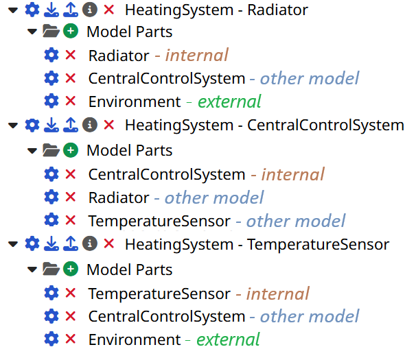
Here is an example of what it could look like after creating all the needed Model Parts:
-
-
Configure the flows in the executable:
Each flow is defined by a source and a target, both of which are based on Model Parts. However, these need to be explicitly configured.
-
For each flow of each executable, click on the configuration wheel next to the flow.
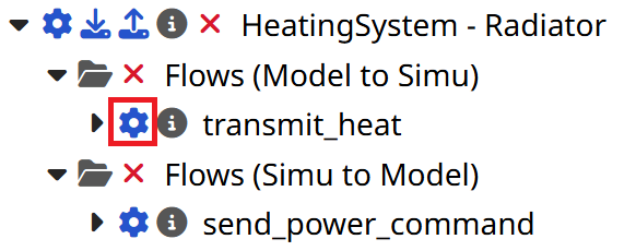
-
Now select both the correct source and the target of your flow, then click "Save".
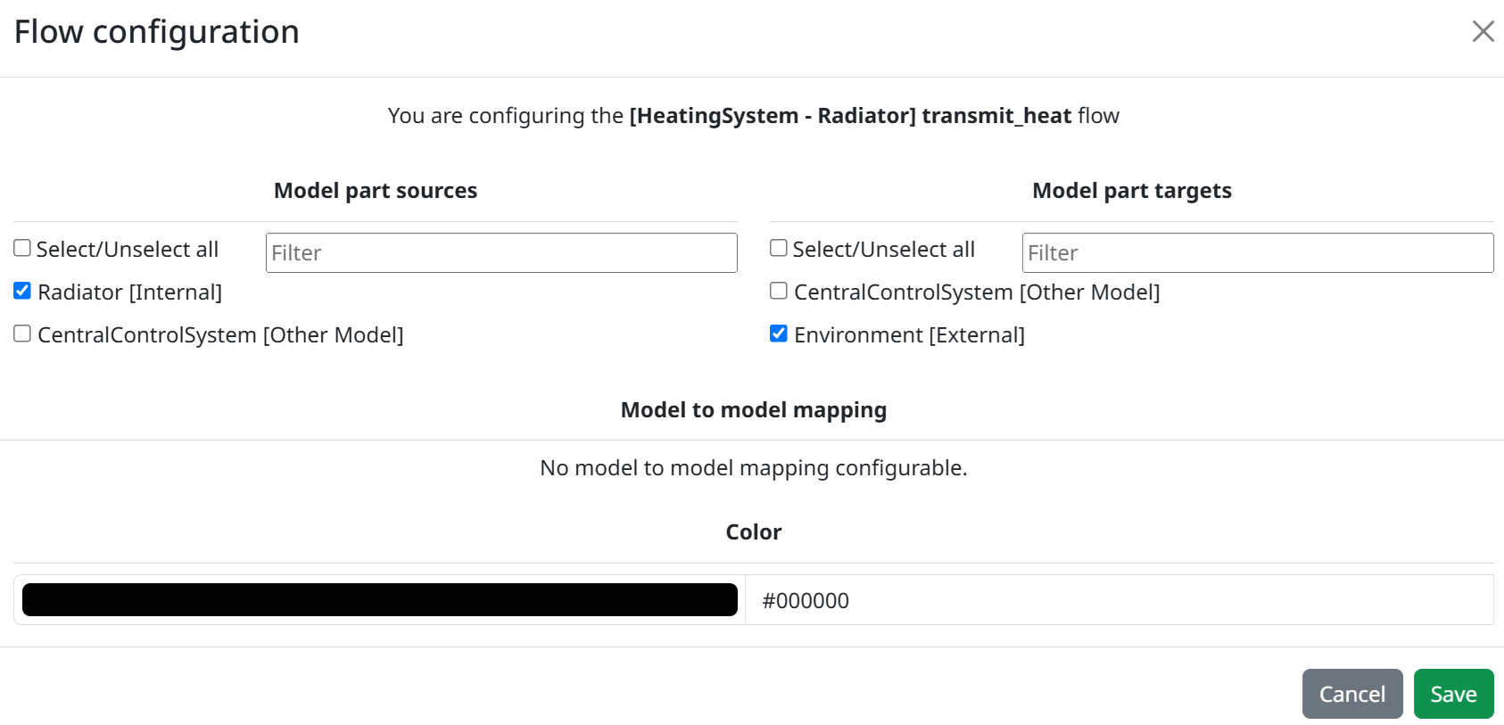
-
Apply those steps for each flow.
-
Mappings
Each flow that travels from one executable to another needs a corresponding flow on the other side. This step ensure that those two flows are linked together, using a Model to Model type mapping.
-
Click on the '+' icon next to the "Model to model mappings" folder in the Project tab in order to add a new mapping.
-
Create the model to model mapping by selecting the source executable as well as the flow it sends, and the target executable as well as the flow it receives.

-
Click "Save", and if needed, map the parameters between them to transmit any needed data before clicking "Save" again.

-
Repeat these steps for all the inter-model links that you can think of. In our case, there are only two:

Creating a New Scenario in Virtual Bench
Create a new scenario in Virtual Bench.
Before creating and using the sequence diagram, you will need to instantiate the previously created model parts in your scenario, as well as the model to model mappings.
Step 1: Create the Websockets
In the Scenario tab, in the Websockets folder, create a new websocket for each executable.
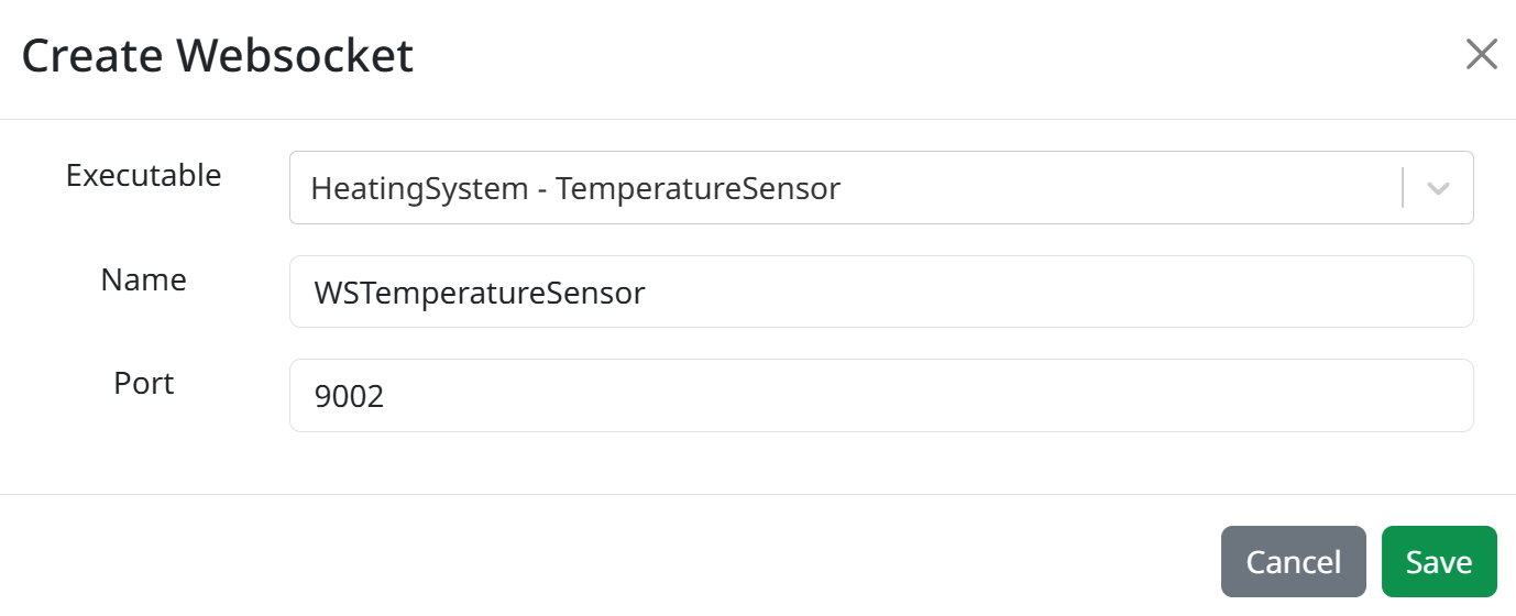
Step 2: Add model part instances
-
Ensure that every websocket has been created.

-
For each Websocket, you will find a folder called "Model part instances", click on the '+' icon next to it.
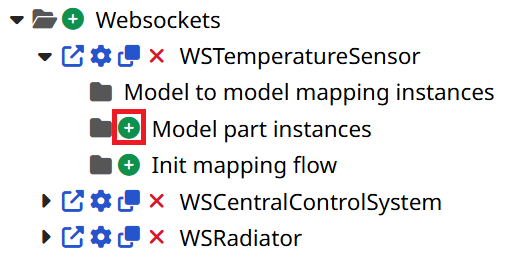
-
From there, you can choose a model part, and click Save. If the model part references another model, choose the related Websocket when asked.
-
Repeat this step, as many times as there are Model Parts to instantiate.
-
You should now see all the instances under the Model part instances folder, as such:
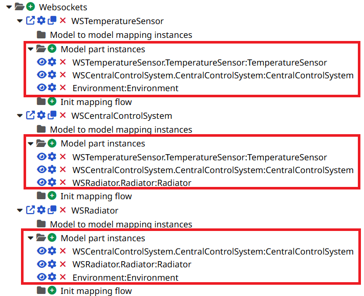
Step 3: Add model to model mapping instances
In the scenario tab, in the "Model to model mapping instances" folder, instantiate the mappings that you have previously created.

Do this until there are no model to model mappings to instantiate. In our case, there are two instances to add.
Step 4: Set up the Sequence Diagram
In our case, we will be configuring the Sequence Diagram, to visualize operational flows between our models.
-
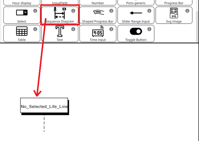
In any HMI context, in Edit Mode, add a Sequence Diagram by drag & dropping the element. The sequence diagram should not be configured and should display "No Selected Life Line".
-
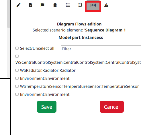
By selecting the element or double-clicking on it, open the element tab to the right-hand side. Open the Diagram flows tab, by clicking on it.
-
Select all model part instances in the order you want them to appear from left to right.
NoteYou can still change the order later by right clicking on the sequence diagram, and choosing the "Edit and sort model parts/flows" option.
NoteThe External actors such as "Environment", whose Model Parts have been instantiated more than once, may appear several times. If you gave them the same name (in our case "Environment"), such actors will be merged and will appear as one unique lifeline.
-
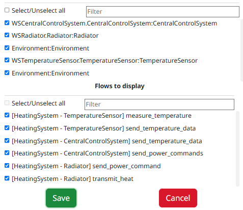
Automatically, you should see all the eligible flows, relative to their sources and targets. If you want them in the visualization, select them too. In our case we will be selecting them all.
-
Click "Save", this should update the sequence diagram.
Run the scenario
-
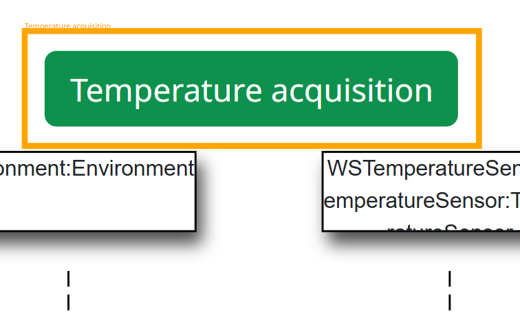
Create a way to trigger the first flows of your scenario. In our case, the Environment giving its measure to the temperature sensor should be the initial trigger. Create a button to visualize the initial trigger, along with the associated mapping.
-
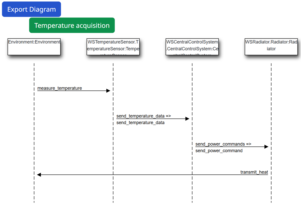
Run the scenario. After the initial temperature acquisition from the Environment, the scenario should unfold, displaying the different flows step by step.
Conclusion
By following this tutorial, you've learned how to visualize dynamic system interactions at an operational level, using sequence diagrams in Virtual Bench. After configuring your scenario and flows, you were able to create a sequence diagram that visualizes how models interact with each other. You should now be able to use this knowledge with more complex sequences.