Sequence Diagram
This element represents a Sequence Diagram, where the lifelines align with the model part instances, and it is necessary to configure the flows.
All configurations are accessible in the right sidebar under the "Sequence diagram parameter" tab.
Simply choose the desired lifelines and flows for display by selecting the corresponding checkboxes:

If you click on any of the interactions in the Sequence Diagram, a label with all its parameters will appear on the screen.
When the user pauses the simulation, an 'Export' button appears next to the diagram, allowing the user to export an SVG snapshot of the sequence diagram in its current state.
This element must be used with HMI context.
Ordering lifelines
You can arrange the lifelines in your sequence diagram to suit your needs once your model parts are instantiated in your scenario.

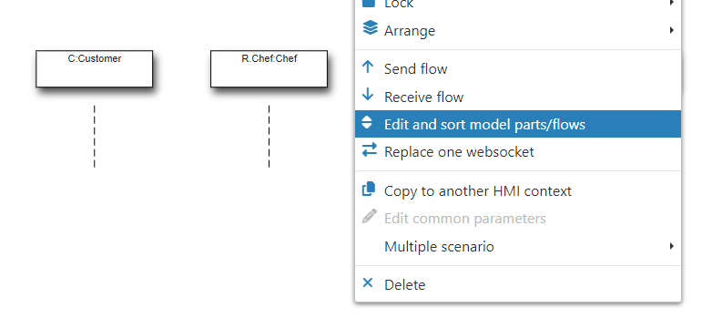
To reorder your lifelines, right-click on the sequence diagram and select "Edit and sort model parts/flows" from the available options:
You can now drag and drop the different lifelines up or down to arrange them in the desired order. Additionally, you can remove lifelines by dragging them to the left box, and add lifelines by dragging them to the right box.
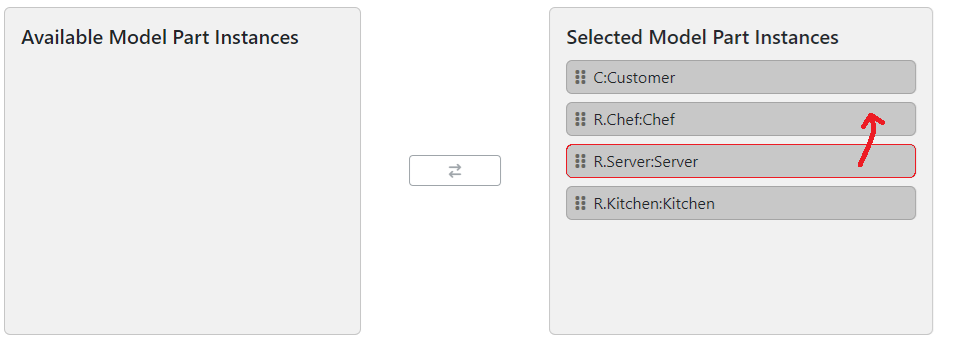
Click Save when you have arranged the lifelines in the desired order. The previous step should organize the lifelines as specified:

Changing colors
You can change the color of both lifelines and specific flows between lifelines.
To change the color of a specific lifeline, go to the Project tab and find the associated executable in the Executables section. In Model parts, you will find the different lifelines that can be instantiated into your scenario. Each can be edited to be associated with a specific color:


Still in the Executables section of the Scenario tab, you can find a specific flow in both the "Flows (model to simu)" and "Flows (simu to model)" folders. By opening the flow configuration, where you can change the sources and targets of the flow, you can also change the color of this flow:
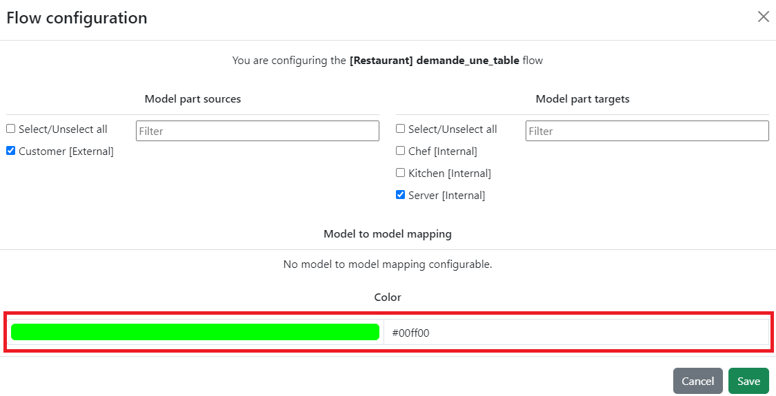
Each time the flow is supposed to appear in the diagram, it will appear with the color previously set:

Condition marks
Condition marks can be used to display an internal value or state sequentially.
To create this kind of display in your sequence diagram, you first need a simulation flow directed to the Engineer in your modeling tool. This flow must carry the parameter you want to display. In the example below, the simulation flow "SIMU_send_led_state" carries the LED state.

In Virtual Bench, after setting up all the other necessary flows along with their model parts, you will also have to configure the simulation flow. To designate this flow for condition marks, you will need to select the relevant model part as a target, and as a target only.

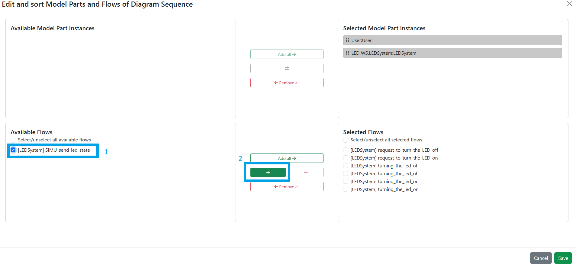
For the condition mark to actually be displayed, you must add the simulation flow to the list of flows to display. To do this, in Edit Mode, right-click on your sequence diagram and select the Edit and sort model parts/flows option. In the Available Flows section (bottom left), select the relevant simulation flow and click the "+" icon to add it to the Selected Flows section (bottom right). Finally, click Save.
It should be all set. When running the simulation, the condition marks should look something like this:

Internal activity Representation
Internal activities can be displayed to show what is happening inside a system or sub-system.
First, you need to create a simulation flow connected to the Engineer in your modeling tool.
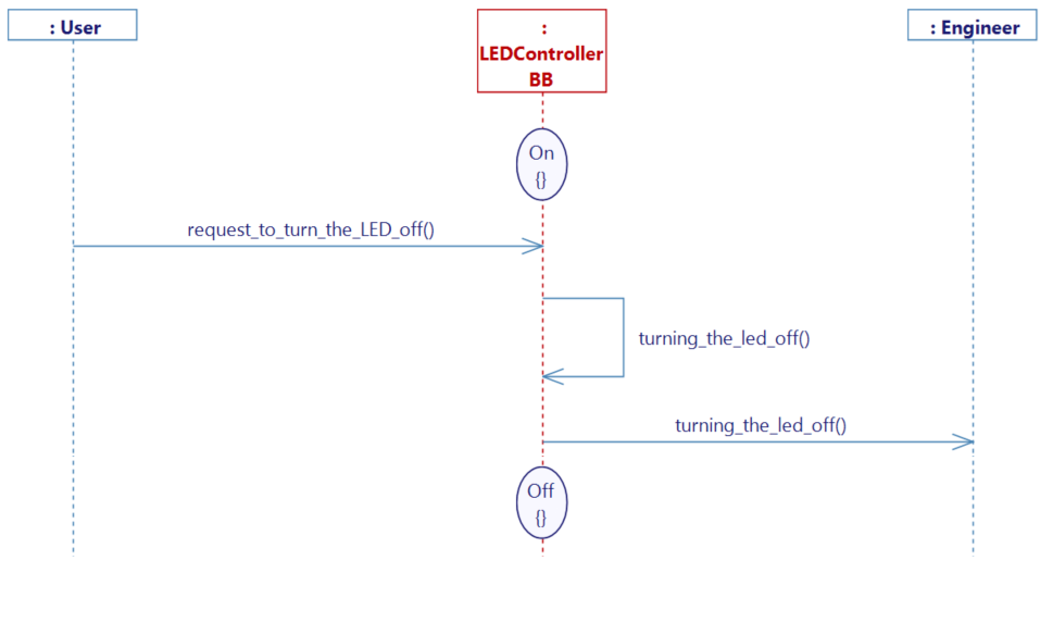
When opening the configuration of your simulation flow, you will need to select the relevant model part as both a source AND a target.

In Edit mode, add the simulation flow to the list of flows to display.
When running the simulation, the internal activities should appear:
Icon

HMI Representation

External parameters
You can edit the units
Show/Hide all parameters
| parameter | editable via "Parameter" tab | updatable via a mapping | description | default unit | type |
|---|---|---|---|---|---|
| X-axis position | ✔️ | ✔️ | Position of the element on the X-axis. | px | Integer number |
| Y-axis position | ✔️ | ✔️ | Position of the element on the Y-axis. | px | Integer number |
| Width | ✔️ | ✔️ | Length of the element on the X-axis. | px | Integer number |
| Height | ✔️ | ✔️ | Width of the element on the Y-axis. | px | Integer number |
| Visibility | ✔️ | ✔️ | This parameter allows you to choose if you want the element to be visible or not on the scene during the execution of the scenario. If the item is part of a group, it can inherit the value of that group. | - | Enumeration (visible, hidden, inherit) |
| Angle | ✔️ | ✔️ | Angle of rotation of the element compared to its initial position. | degree | Decimal number |
| Model parts | ❌ | ❌ | List of selected model parts to display. | - | Array of Text |
| Flows | ❌ | ❌ | List of selected flows to display. | - | Array of Text |
| Update period | ✔️ | ✔️ | Periodically update the diagram. | - | Decimal number |
Triggered behaviours
See Triggered behaviours and events page for more explanation: Triggered behaviours and events.
Show/Hide all triggered behaviours
Destroy
At the reception of the flow, the element is destroy.
No parameters for this triggered behaviour.
Events
See Triggered behaviours and events page for more explanation: Triggered behaviours and events.
Show/Hide all events
| event | description |
|---|---|
| On Parameter Value Changed | The element can send information to the model when the value of the selected parameter has changed |
| At initialization | The Sequence Diagram can send information to the model once at initialization |
| Continually | The Sequence Diagram can send information to the model continuously |