New Service Sequence Diagram
The Sequence Diagram allows us to detail the progress of a case, in the sequential order that those interactions occur, and indicates the information exchanged.
A Sequence Diagram allows to tell the story of a User Story (hence the name). This story begins with a trigger and continues with events, if all conditions are met. That's what we call a requirement.
CREATE A USER STORY IN A USE CASE
Creation
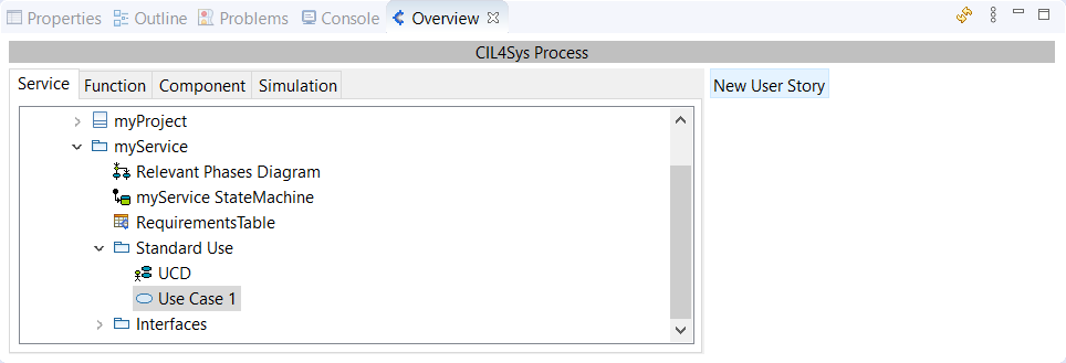
To create a User Story, select a Use Case package in the CIL4Sys Overview and click on New User Story:
Type the name of the user story and click on OK:
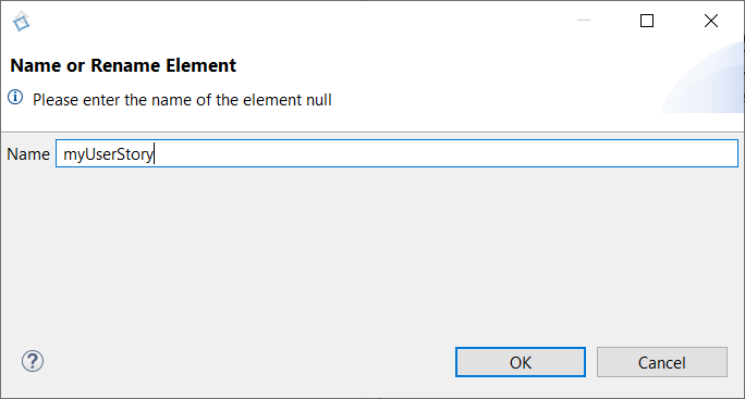
Naming rule: User Story naming consist on a short description of the story Example: The user requests to activate the function
Your User Story is available in the stucture tree:
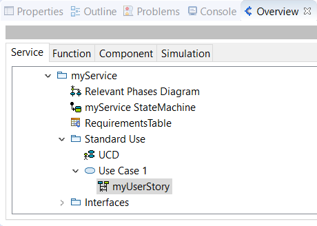
This action creates two sequence diagrams:
- One for service level
- One for functional level
Navigation between service level and function level sequence diagram is done by right-click and select "Open linked sequence" on the diagram:
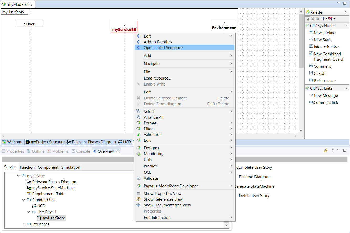
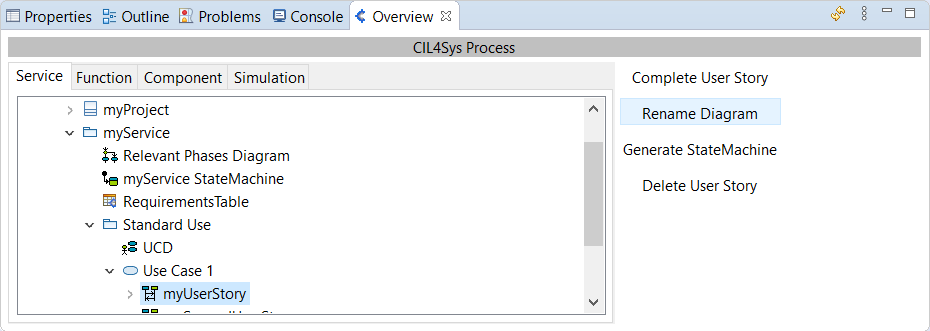
User Stories can be renamed by clicking on "Rename Diagram" in the Overview.
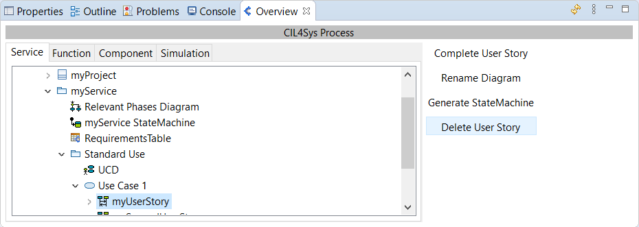
In the same way, their can be deleted by clicking on "Delete User Story".
Rename a User Story
You are able to rename a User Story by clicking on Rename Diagram:
Delete a User Story
You are able to delete a User Story by clicking on Delete User Story:
Organize User Stories
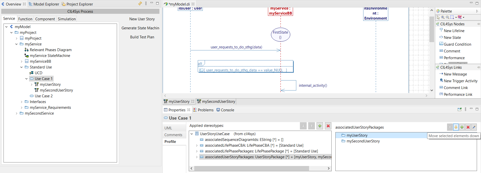
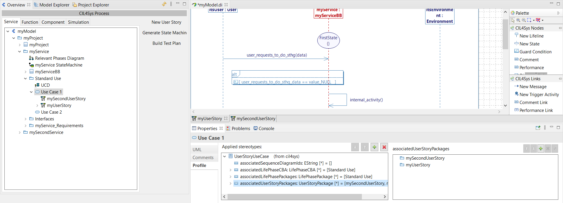
You can organize your User Stories as you see fit in a Use Case. To do this, simply do a "Move Up/Move Down" of User Stories, via the Properties of the Use Case > Profile > UserStoryUseCase > associatedUserStoryPackages, as below:
Once you made your modifications, refresh the Overview to notice them:
Move a User Story from a Use case to another
You may need to move a User Story from one Use Case to another.
You will need to add an association between the User Story and its new Use Case, and delete the old one (only one operation is required to perform the change at the Black Box and White Box levels).
On the one hand, you have to go on the Properties of the actual Use Case > Profile > UserStoryUseCase > associatedUserStoryPackages and delete the association by clicking on "Remove selected elements" cross button:

On the other hand, you have to go on the Properties of the new Use Case > Profile > UserStoryUseCase > associatedUserStoryPackages and add the association by clicking on "Add elements" button:

A new pop-up will open, allowing you to select the User Stories to associate:
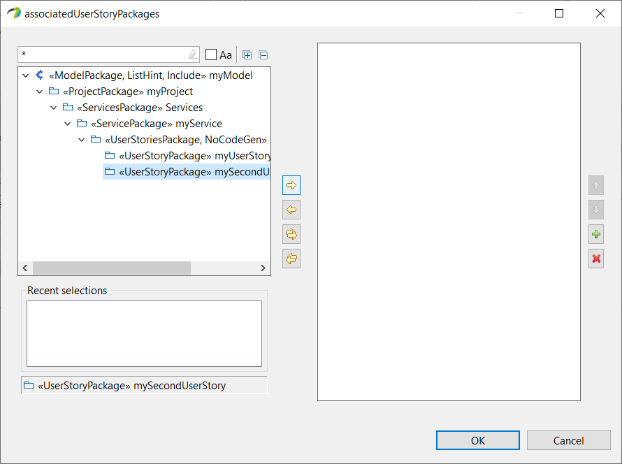
Scroll down the tree until you find the User Stories Packages and use the arrows in the middle to pour the ones you want to add, then click "OK".
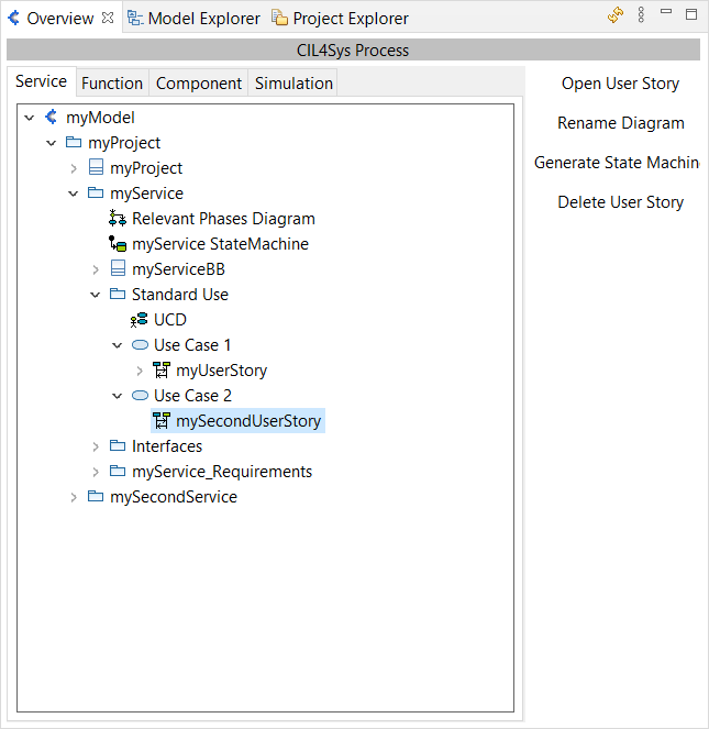
After a refresh of the Overview tab, you will see the correct move of your User Stories:
COMPLETE THE USER STORY
State
To complete the new User Story, in the Overview, double click on the user story, or click on "Complete User Story", in order to open its relatice Sequence Diagram.
It has three life lines: User, Service & Environment, as below:
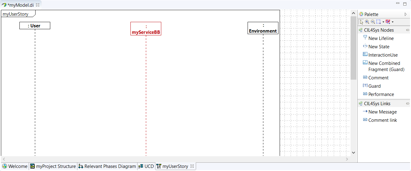
Initial condition is mandatory to start a sequence diagram.
You can do it by Drag&Drop a New State on the Service lifeline, a list of existing States in Service State Machine is displayed:
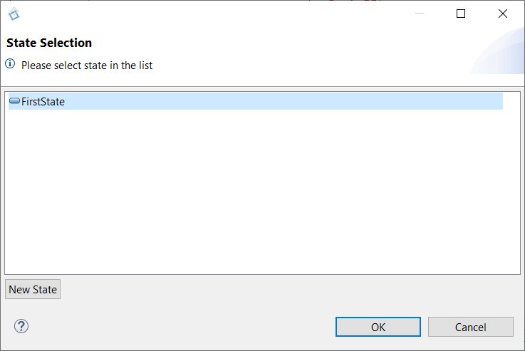
By default, the state "FirstStep" is available. You can rename it after creation or by the Properties view of Papyrus
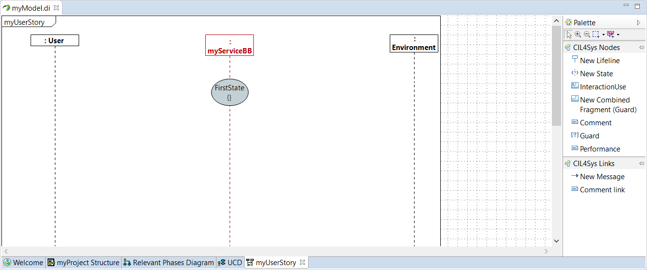
Naming rule: State naming consist on an adjective. Examples: Activated ; Programmed ; Turned_Off
A State Machine inventories the different states that can have a Service, and also shows discrete behavior of a part of designed system through finite state transitions.
You can add other states by clicking on "New State" in the State Selection window. It will open the State Machine Diagram, you only have to Drag&Drop a New State (more details in State Machine page)
Create Messages
You can create an information flow between functionalities, by tracing a New Message between two lifelines.
Depending on the lifeline, you will have:
- Requests from User to Service
- Feedbacks from Service to User
- ENV inputs from Environment to Service
- ENV outputs from Service to Environment
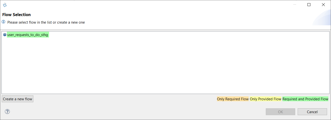
A new window will list these existing operations:
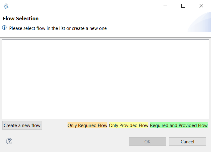
Select an existing one and click on "OK", different color codes are used to inform you about the flow connection state.
Or click on "Create a new flow" to create an operation, it will open an "Interfaces Diagram":
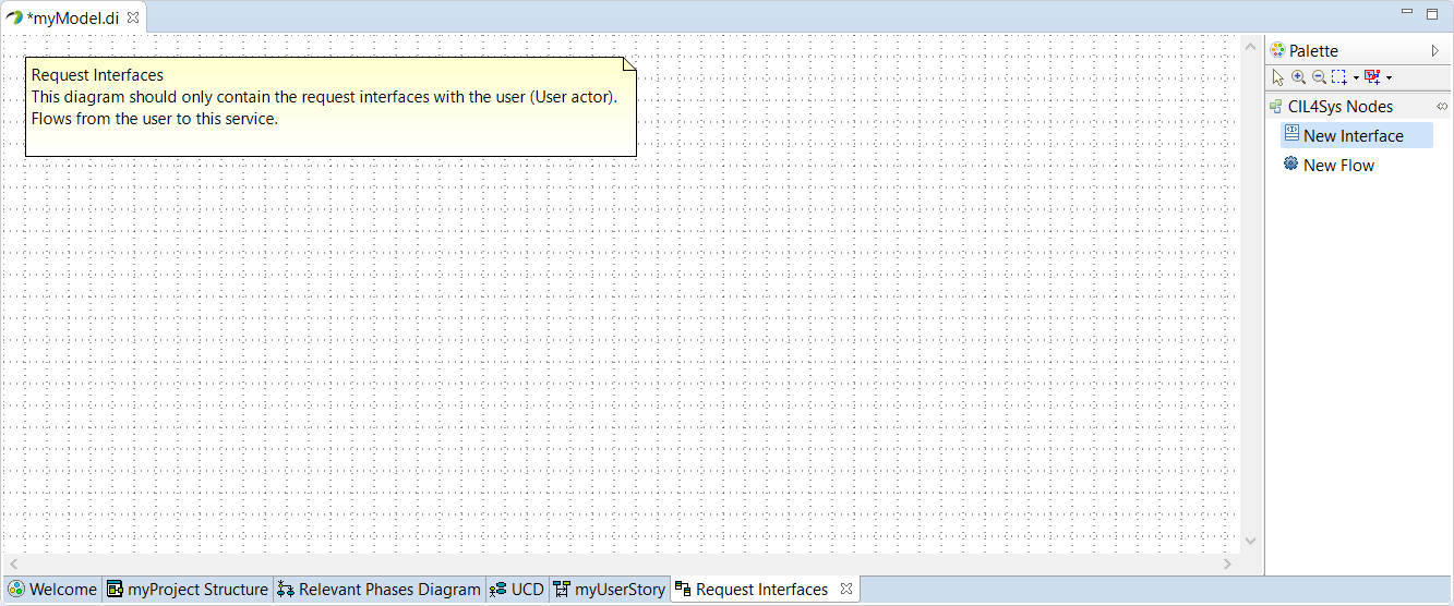
This new operation needs to be defined in an interface.
Interfaces
To allow the life lines to exchange information, we need to define the communication interfaces.
If you try to create an operation without suitable interfaces, the software will ask you to create them.
Depending on the impacted life lines, we can have different Interfaces:
- Request (between Customer and Service)
- Feedback (between Service and Customer)
- ENV Input (between Environment and Service)
- ENV Output (between Service and Environment)
- Inter Service (between two services inside the same project)
To create an interface, Drag&Drop a New Interface on the "Interfaces Diagram":
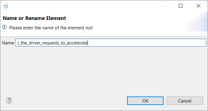
Naming rule: Interface naming consist on "I_" followed by the name of the flow Examples: I_Requests_to_activate ; I_Inform_of_activation
Type the name of the interface and click on OK:
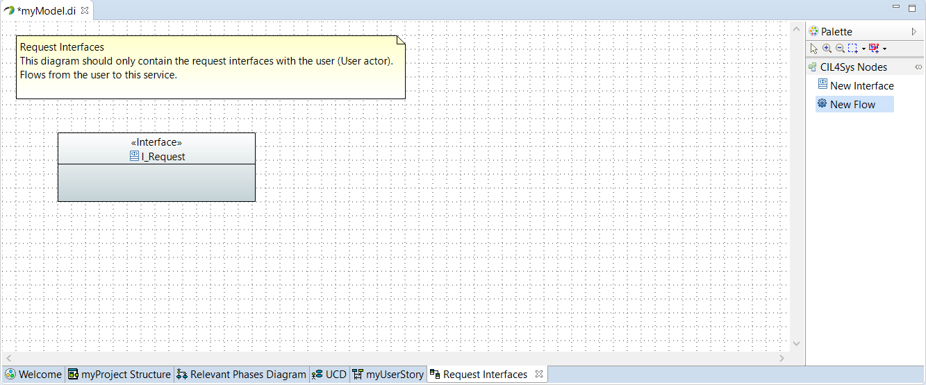
Now, you need to add operations by Drag&Drop a New Flow in the newly created interface:
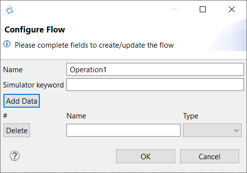
You can:
- Name your operation
- Add parameters to your operation via Add Data
- Name these parameters
- Do not forget to define a Type via the drop-down list (by default, you start only with Integer, Decimal and Text types) : See the page Types Diagram. Indeed defining a custom type allows to exchange functional data with complex data structure.

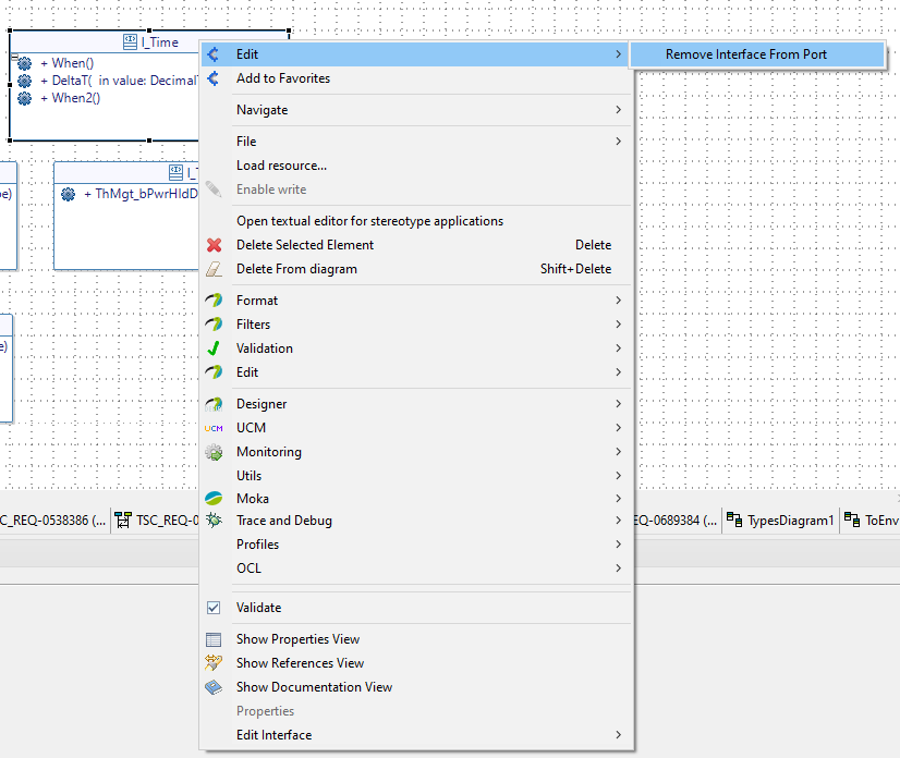
If you want to remove an interface from this diagram, you are free to delete it if you do not want to use it anymore, or if you want to reaffect it in another diagram, you can right click on it and then chose "Edit" -> "Remove interface from port". This way you keep the interface in your model without using it anymore in the previous Interface Diagram.
Trace messages
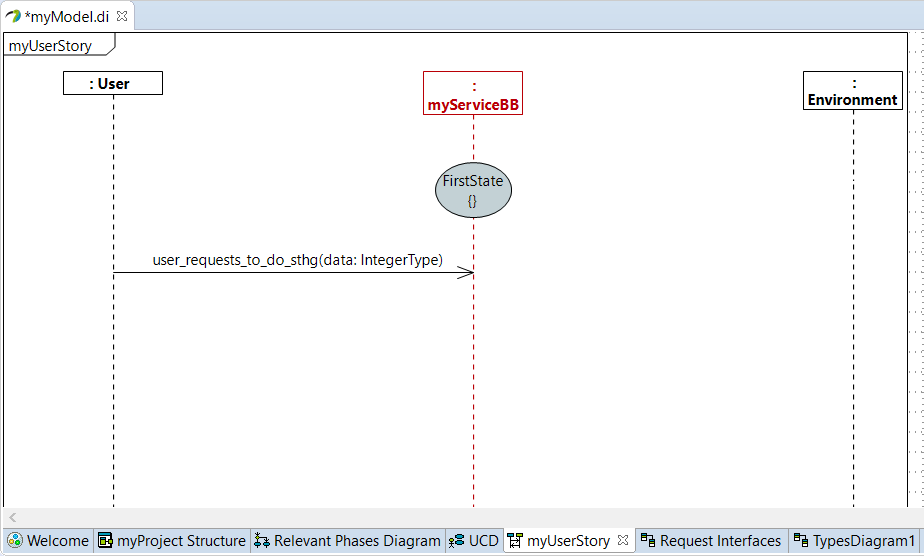
Go back on the user story, re-trace a New message between user and the service and select the newly created flow:
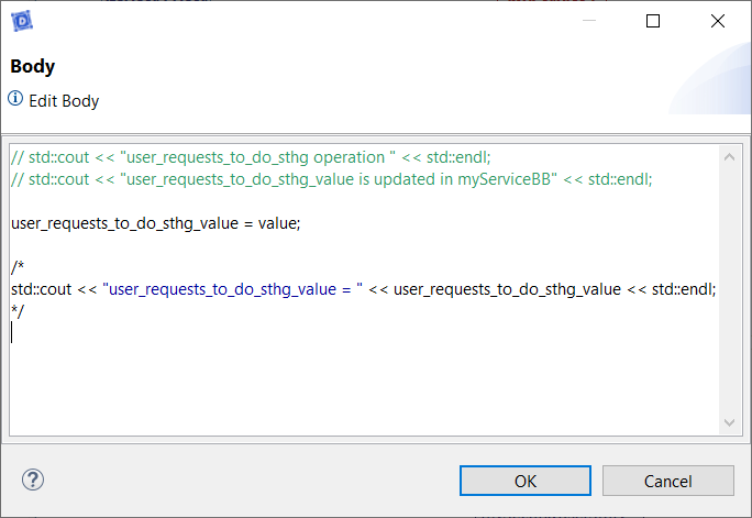
You can access the body of the flow by right-clicking on the flow then Edit -> Edit body. By default the display of the flow and its values are commented. You can uncomment it to display the text on the console of the executable during the simulation.
Modify flows
Stored parameters are automatically created for each data in the flow into the service package, with the following name rule: FlowName_DataName.
You can modify a flow (rename the operation, add or delete parameters, change the type of a parameter), by right clicking on the operation and selecting "Edit > Update Flow", it will open the same previous window. The corresponding stored parameters will be impacted too.
You can add as many parameters as you want, delete parameters by clicking on "Delete". When you are satisfied, click on "OK" to take these changes into account.
These modifications are automatically applied to all diagrams.
The data forwarded by the flow are automatically stored in the Service, corresponding to the new parameters created previously. These stored data will be used subsequently during tests.
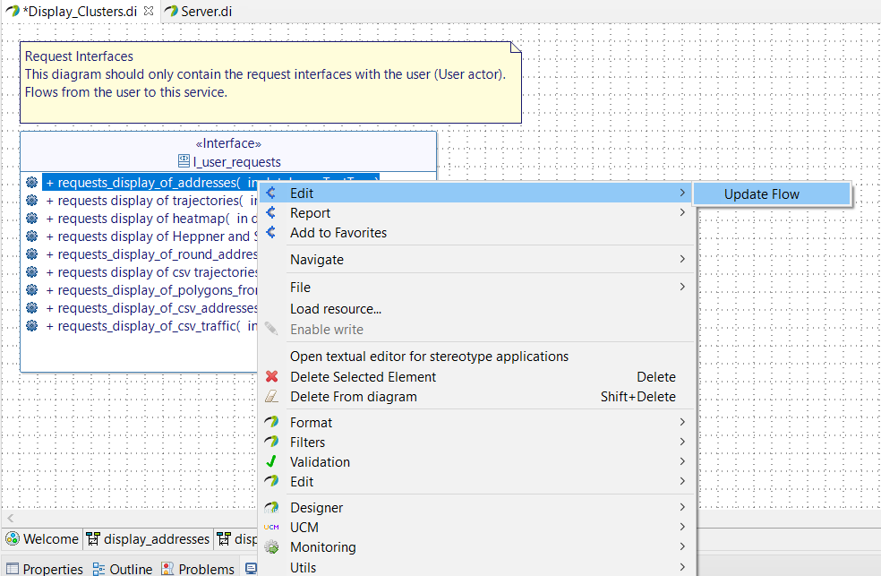
Only this method allows the automatic renaming of all elements associated with the flow (messages in diagrams, parameters, etc.). Otherwise, the dedicated script will not be applied and you will end up with compilation errors, due to undefined elements.
Delete flows
You can delete a flow by right clicking on the operation and selecting "Edit > Delete Flow". The associated stored parameters will be deleted too.
If this flow was present in one or more sequence diagrams, you will be warned:

If you confirm the suppression, impacted diagrams are listed in Assistant tab:

You find the Message ID, the Service impacted, the linephase emitter and the User Story impacted.
You just have to delete the messages in each User Story impacted.
Guard Condition - Test of value
A Guard Condition on a flow consist in one or more comparisons between variables and parameters into a test.
The variables are data forwarded by a flow and stored in the Service (review Interfaces).
The parameters are fixed data, inquired by the Service designer, in order to be compared to variables during tests.
If the condition is true, the information can continue the path.
Else, the information stops.
If you need to add a condition on an operation, Drag&Drop a New Combined Fragment (Guard) on the diagram:
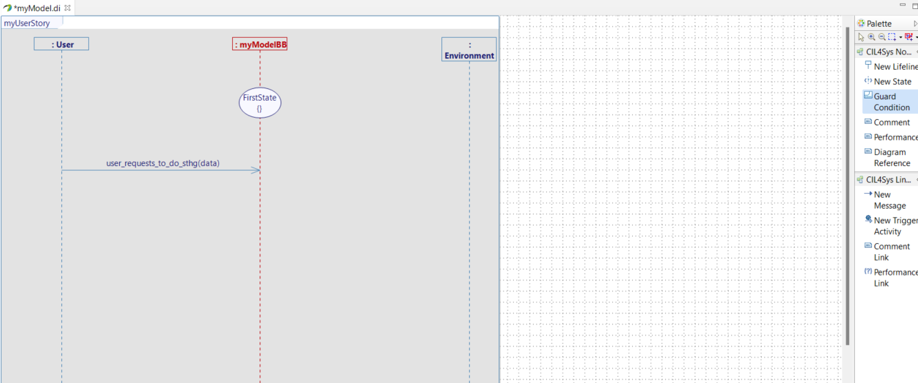
A new window will open:
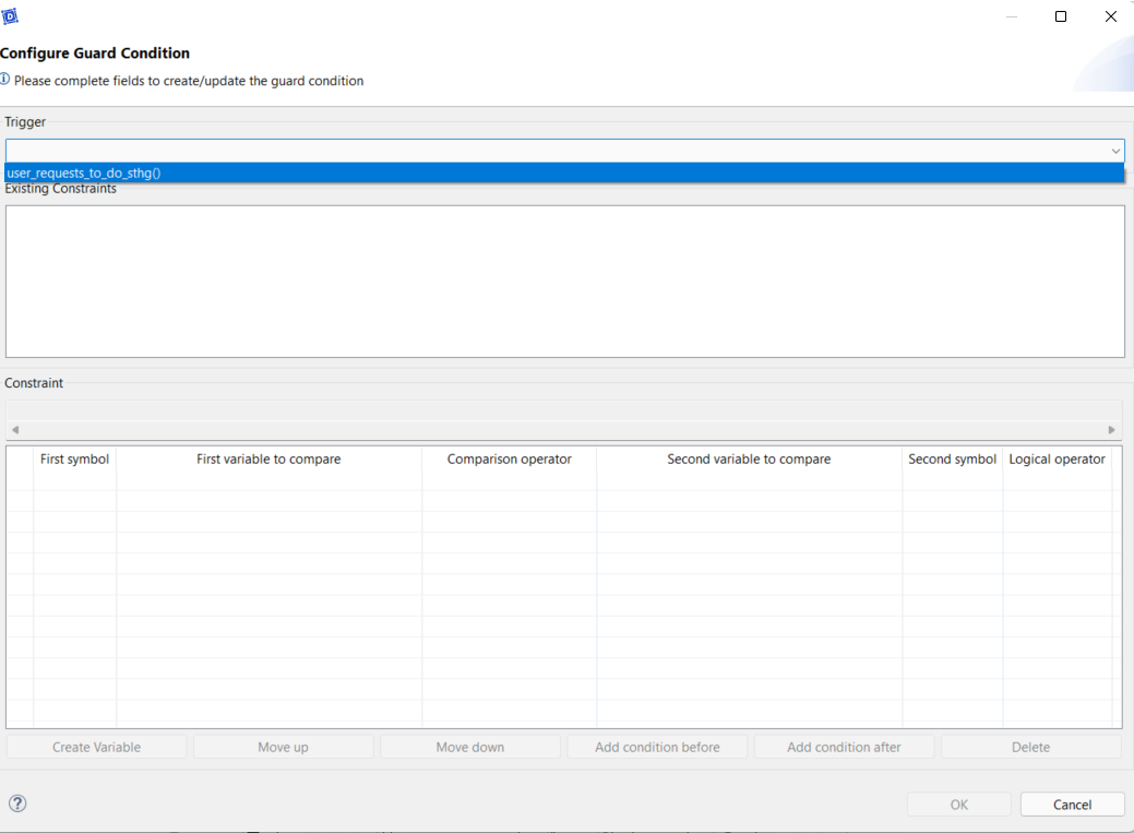
First of all, you have to select a trigger to attached the guard (only operations present inside the diagram are listed).
Then you can "Add Condition":
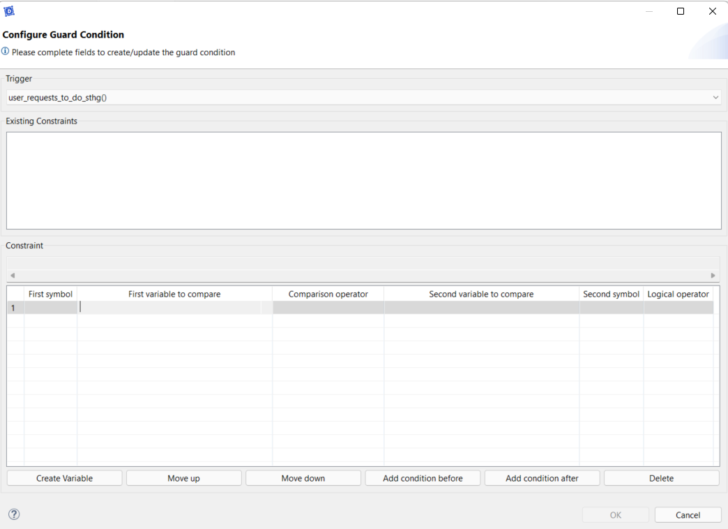
First column: possibility to define an opening parenthesis.
Second column: This is the list of the stored data, it is not possible to create a new one via this window, because a variable should be created or modified by a flow from the outside of the Service.
Third column: Select the logical comparison operator used for the test:
- is strictly less than
- is strictly greater than
- is less than or equal to
- is greater than or equal to
- is equal to
- differs from
Fourth column: this is the list of parameters to compare. These parameters can be stored data, a variable or a constant define in the Service.
Only parameters with the same type as the stored data are listed.
Fifth column: the list of the different logical operators available (AND & OR).
Sixth column: possibility to define a closing parenthesis.
Inside the white window, you can find the list of all Guard Conditions already used for the selected flow. You can select one and it will be load immediately in the columns.
Click another time on "Add Condition" creates an additional line:
- "before": adds the line before the selection
- "after": adds the line after the selection
"Create variable" opens the variable creation pop-up on top of the Guard Conditions.
"Move up" moves the selected line up a notch.
"Move down" moves the selected line down one notch.
"Delete" deletes the corresponding line.
"OK" validates your choice and creates the Guard Condition.
"Cancel" stops the creation of the Guard Condition.
- severals guard conditions for the same trigger should be mutually exclusive : if not, at execution, only one transition will be executed, and not the others.
- to model an "else" guard condition, you have to create a guard condition that is the negation of the union of the other guard conditions for a same trigger.
You can select multiple lines at the same time with Ctrl, to move or delete them with a click.
In the diagrams, a Guard Condition must follow its relative flow.
If you ever have a succession of Conditions and you no longer know which one corresponds to which trigger, you can right-click on the Condition Navigate > Go to trigger > [Sequence Diagram Name]:
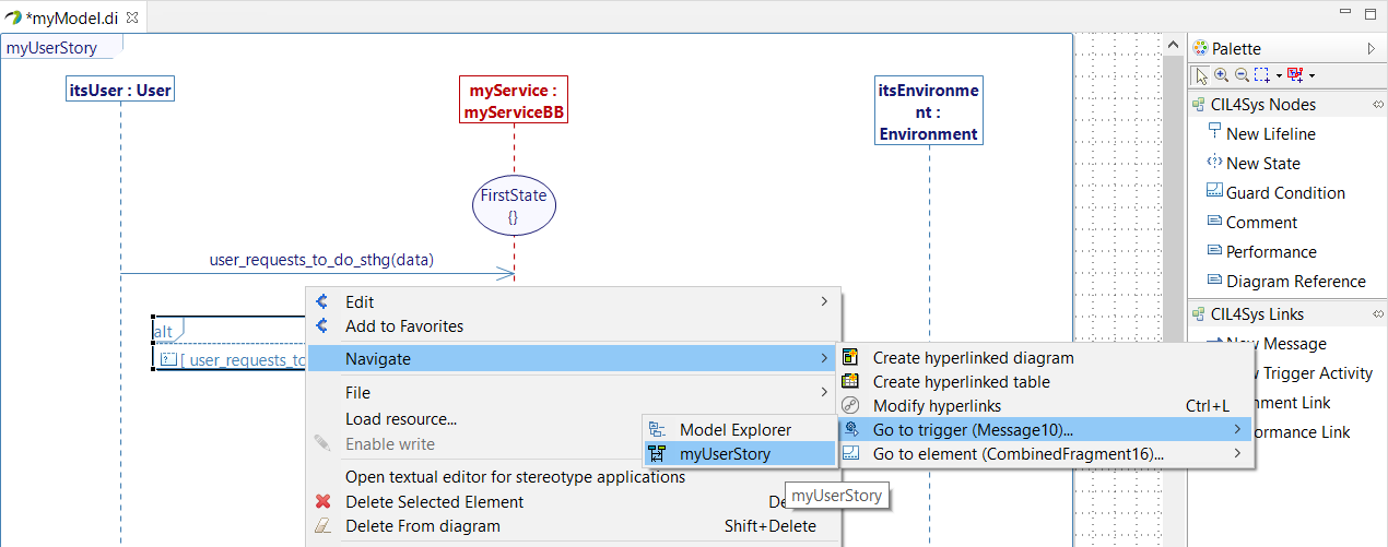
This will return you to the corresponding trigger.
Do not upsize the "alt" on the top left of the Guard Condition, it must not have any flux or activity inside it.
If this condition is not respected, it can create issues when you delete or regenerate transitions for the State Machine.
The same flow used as a trigger must be accompanied by exclusive conditions, otherwise, only the first transition whose condition is true (in the State Machine) will be executed and the others ignored.
Create a Variable or a Constant
We just saw that a condition needs to be compare to a variable or a constant.
To create on, right-click on a linephase and select Edit > Create Variable or Create Constant:
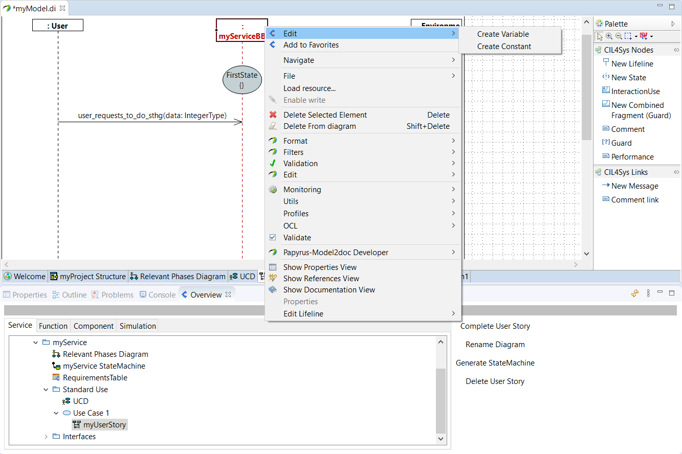
A new window will open (common for both variable and constant):
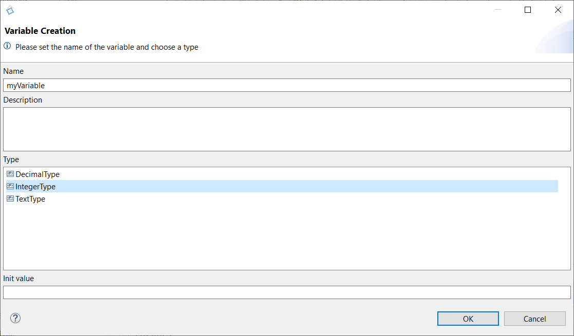
Give a name, a description (optional) and a type to your variable or constant. Once you select a type, give an init value if it is a primitive type or an enumeration.
Naming rule: For a Constant, naming should be in capital. Examples: MAX_TIME_FOR_ACTIVATION , MAX_SPEED_LIMIT
Modify a Variable or a Constant
Click on the variable or constant in the Overview, inside the "Properties"
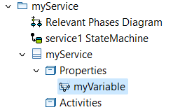
Go to the "Properties"

You can rename the variable by changing its field "Name".
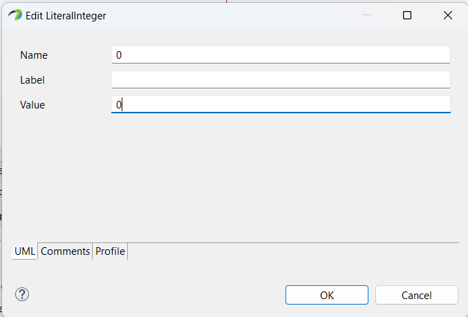
Click on the pen near the Default value field to open a popup allowing you to change the default value of the variable.

Change the "Name" field and "Value" field to the wanted value, and click "OK":
Internal Activity
An internal activity has input variables and output variables, and an algorithm modifies them.
Go back to the User Story and trace a New Message between the service lifeline on itself.
The below window allows you to select an existing activity:
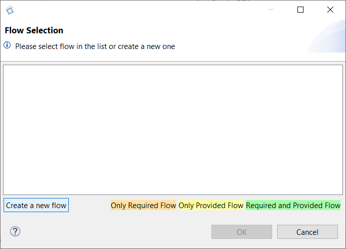
But you can define a new one by click on "Create a New Flow":
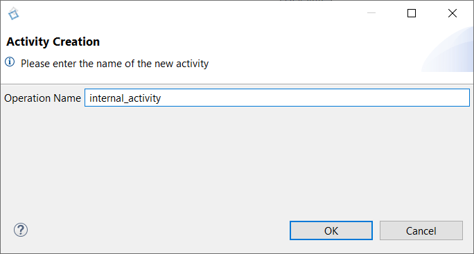
Type the name of the activity and click on OK, the activity is added in the diagram:

It is possible to create variables relative to an internal activity by right clicking on it and select "Edit > Create Variable":

If you want to fill the body of your activity with C++ code, you must right-click on it and select Edit > Complete Activity, then in the pop-up, select Code C++.
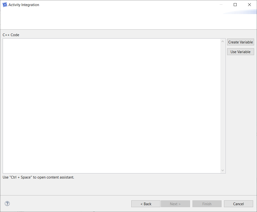
"Create Variable" opens the variable creation pop-up on top of the Guard Conditions.
"Use Variable" opens a pop-up listing all variables of the same Life Line as the activity.
By clicking on Ctrl+Space, you will have access to a content assistant, which will help you fill your code with:
- Type & Enum literal of the Project,
- C++ keywords,
- C++ snippets (for loops, if... else, while loops, etc.),
- Variables & Constants of the same Life Line as the activity.
Performance Requirements
A Performance Requirement clarifies the technical content of an internal activity.
In order to explicit the operation of an activity, a Performance Requirement could be created in the Sequence Diagram, by Drag&Drop a Performance inside the diagram:
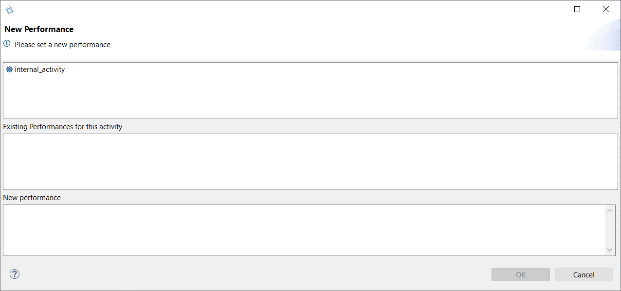
Select an internal activity to attach a performance and describe the technical content, with the possibility to refer to the parameters defined in the Service.
There is no limit number of performance requirements that can be attached to an internal activity. You can find these existing performances in the section with this name.
Once the performance written, click on OK in order to display it inside the User Story.
If the performance text doesn't appear, close the diagram and reopen it;
You can add a link between the activity and its performance, to be more visual, by Drag&Drop a Performance Link:

Diagram Reference
The diagram reference allows you to add links to other sequence diagrams and easily navigate between your diagrams by a simple double click.
This allows you, for example, to list the possible sequences of a User Story, if there is a branch line in your stories.
To do this, simply click on:
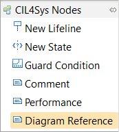
and click on the Sequence Diagram background.
A new window opens, listing all Sequences Diagrams:
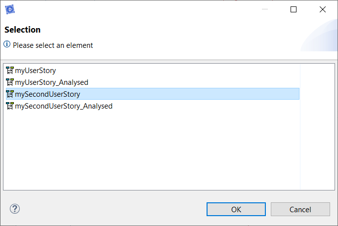
Select the one you want to refer and click on Ok.

Trigger Activities
Sometimes, it is possible that the realization of an internal activity is a trigger for the rest of your story.
For example, you can check a calculation result against a threshold at the end of an activity and perform an action or another, depending on the value of that result.
To do so, after the creation of an internal activity, select "New Trigger Activity" on the right palette.
Then, click one time on the Sequence Diagram background then on the activity's LifeLine, a window listing all LifeLine activities opens.
Select the one you want and click on "OK", you should have that at the end:

Guard Condition - Complex Data
A guard condition can easily check a simple received value that is an Integer, or a text. However, it becomes less intuitive when the data transmitted is complex. As an example, we can have a received composed value that looks like the one below:
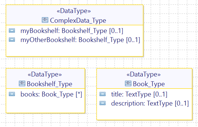
In this case, if we want to extract and test, even just one parameter out of the incoming message, we need to:
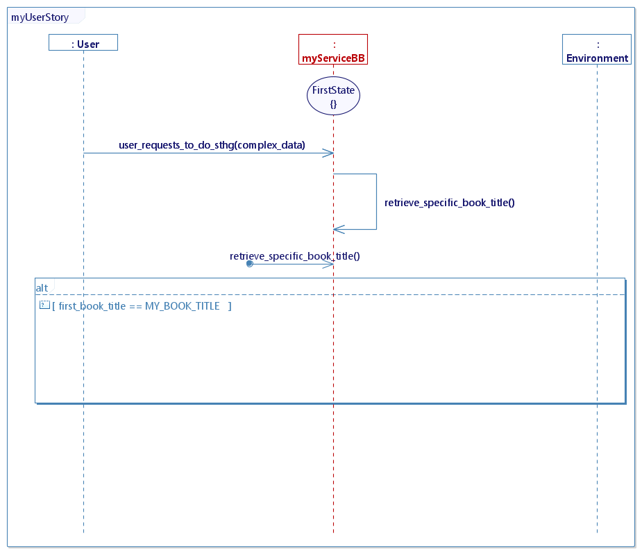
- Create a variable that will hold a specific part of the data that we want to test. (Ex: first_book_title)
- Create a constant that will hold a specific value used for comparison. (Ex: MY_BOOK_TITLE = "My Book")
- Process the data in an internal activity
if(user_requests_to_do_sthg_complex_data.myBookshelf.books.size() > 0) //checking if the bookshelf contains at least one book
{
	first_book_title = user_requests_to_do_sthg_complex_data.myBookshelf.books[0].title; //getting the first book of the bookshelf
}
else //if no book in the bookshelf, assign a default value
{
	first_book_title = "not found";
}
-
Use a Trigger Activity to trigger the guard condition
-
Create a guard condition
In our example, the final result should look like this:
Requirements
Once we have gathered a trigger flow, conditions, activities that may have performance requirements, and feedbacks, we get a requirement.
It is absolutely necessary to have a trigger flow to define a requirement, but it is not mandatory to have all these elements each time. Indeed, a requirement may not have a guard condition, or have no internal activity, or even have no feedback.
Constructional Requirements
A Constructional Requirement explains the real/physical constraints inherent in the Service.
Work in progress
User Manual Requirements
A User ManualRequirement explains that should appears inside the product's user manual.
Work in progress
CONFIGURE A SEQUENCE DIAGRAM
You have the possibility to change the grid and the messages behavior of a Sequence Diagram. Go to the menu Window > Preferences, then select Papyrus > Diagrams > PapyrusUMLSequenceDiagram Diagram and go to the section "Others":
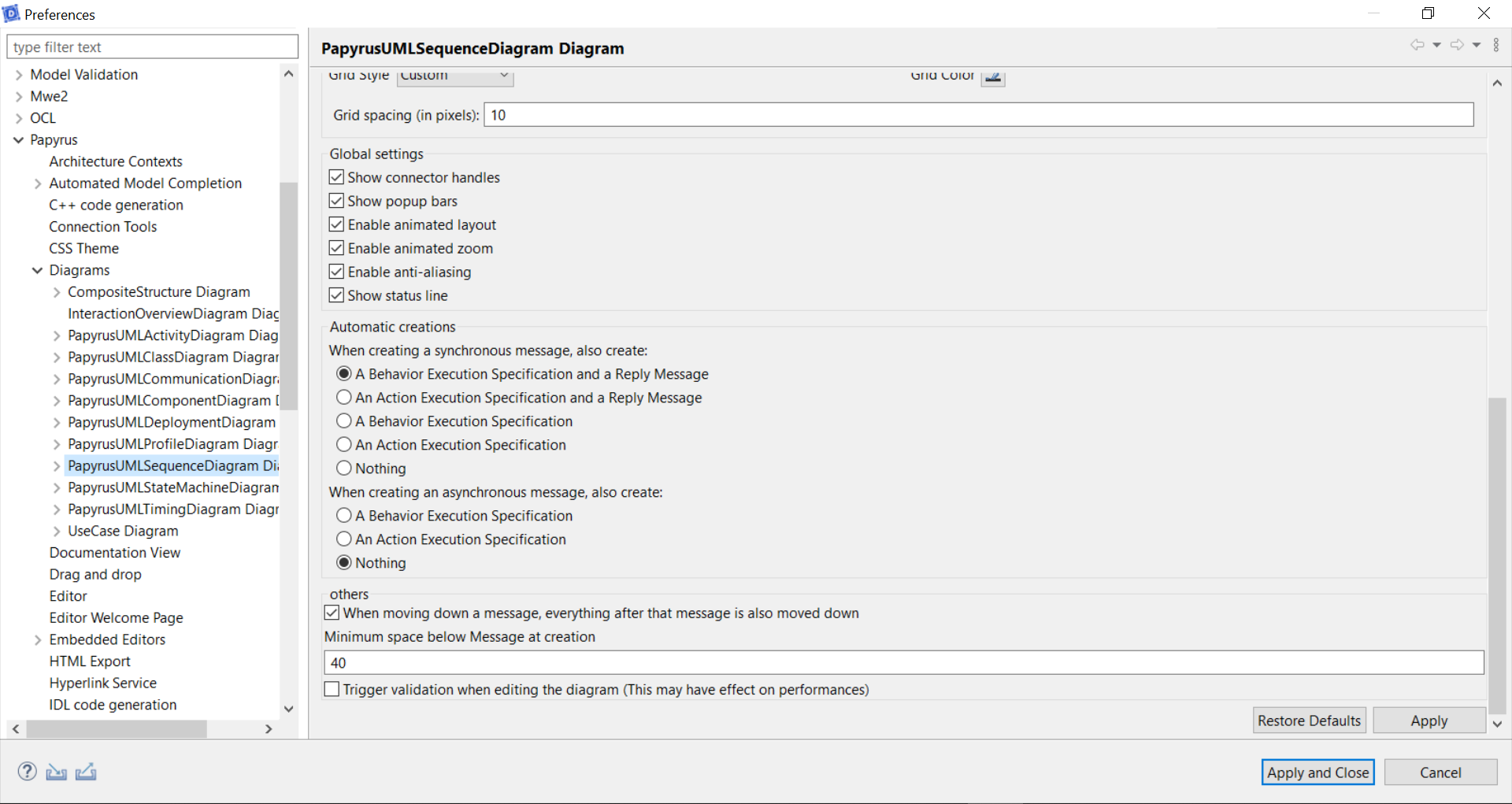
Messages moving down behavior
By default, when you move down a message (flow or activity), all messages bellow move down too. To avoid that, uncheck "When moving down a message, everything after that message is also moved down", you will be able to move a message under another.
Change the grid
In order to help you with alignements, you can change the grid (in pixel) through "Grid spacing". By default, the value is 10px.