Technical Functions Sequence Diagram
As in Service level, the Sequence Diagram allows us to detail the progress of a case, but this time by detailing the interactions between the functions.
ADD FUNCTION LIFELINES
To open to a Technical Functions Sequence Diagram, go to the Overview and double click on your User Story (or select it and click on Complete User Story):

If the Service Sequence Diagram is still open, you can access to the functional one by right clicking on it and select Open Linked Sequence:

Not only does this option allow you to switch from service level to function level, but the reciprocal is also true
A new sequence diagram for Technical Function level opens, with only two life lines: User and Environment:

To add function lifelines, drag & drop a New Lifeline on the diagram and select the functions you need (multiple selection can be made by maintening key Ctrl, or with key Shift if functions follows):

By clicking on OK, function lifelines are added to the diagram:

You can arrange the diagram by drag & dropping the lifelines.
Now, as during the Project Definition level, you can fill the sequence diagram.
You just need to be careful about the Technical Functions Interfaces.
It is possible to change prefix or suffix name of the Technical Functions Sequence Diagram by clicking Window > Preferences > Sim4Sys > Diagrams.
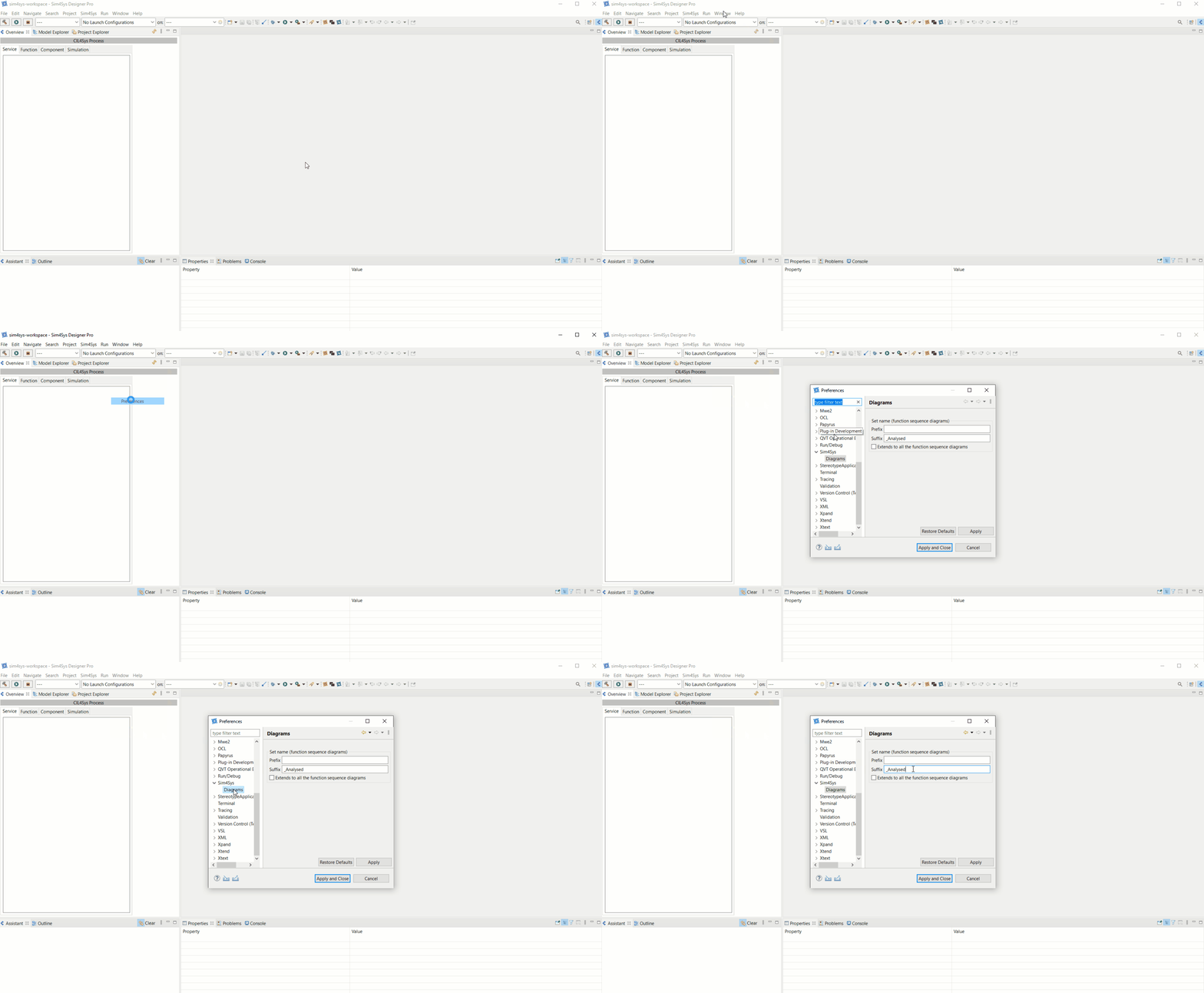
This will not apply to existing diagrams.
TECHNICAL FUNCTION INTERFACES
Modeling Sequence Diagrams requires the creation of Inter Technical Functions Interfaces.
The Functions need to know what they are communicating:
- One interface is broadcasting (Provided Interface)
- Another is listening (Required Interface)
The flows between Functions, called "Inter Function", and their related interfaces are created in "Functions Provided Interfaces Diagram".
Regarding the Required Interfaces, drag & drop the corresponding Provided Interfaces.
During the flow creation, a pop-up will invite you to drag & drop the relative Provided Interfaces:

By clicking on OK, the Provided Interface Diagram will open and the interfaces associated to the selected flow is listed in the Assistance tab:

After the drag & drop, select Existing Interface drag and drop in Class Diagram in the options to finish the connection:

At the end, you have this allocation:
- Service Sequence Diagram:

- Function Sequence Diagram:

We find of course the input flow: "user requests to do sthg" and the internal activity. Everything after it is none other than functional division.
CREATE A VARIABLE OR CONSTANT
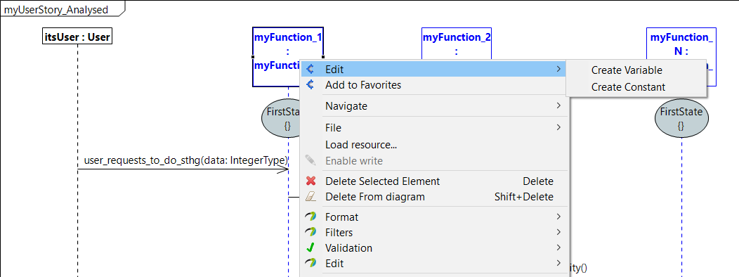
As in Service level, variable and constant creation are the same. Right click on an activity or function lifeline and select "Edit > Create Variable" or " Edit > Create Constant":
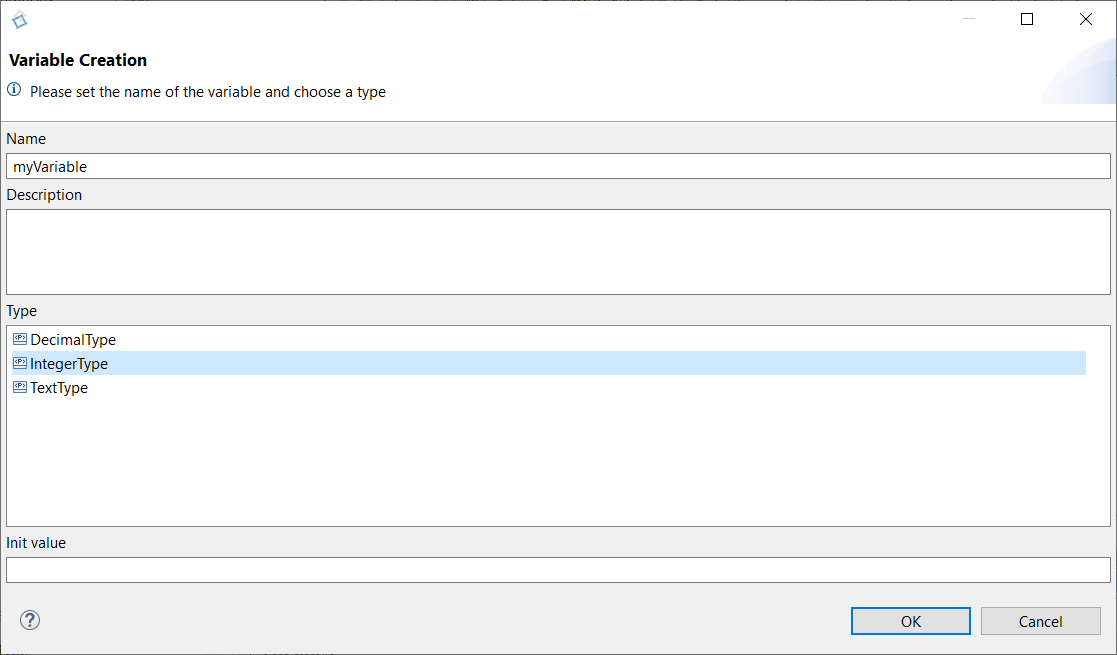
Enter variable or constant caracteristics in the dedicated windows to complete the creation:
COMPLETE AN ACTIVITY
Activities are the theatre of operations influencing the behaviour of the model (calculation of a coefficient, storage of a value...).
These operations are defined inside activity bodies.
To acces to an activity body, right clicking on one and select Edit > Complete Activity:

The following window allows you to choose an implementation:
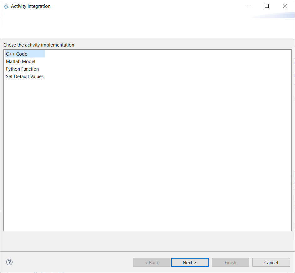
You have four possibilities to complete an activity:
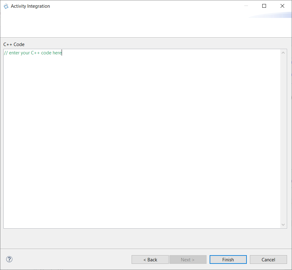
- By selecting "C++ Code" and clicking on "Next", you can enter yourself a C++ code inside the body:
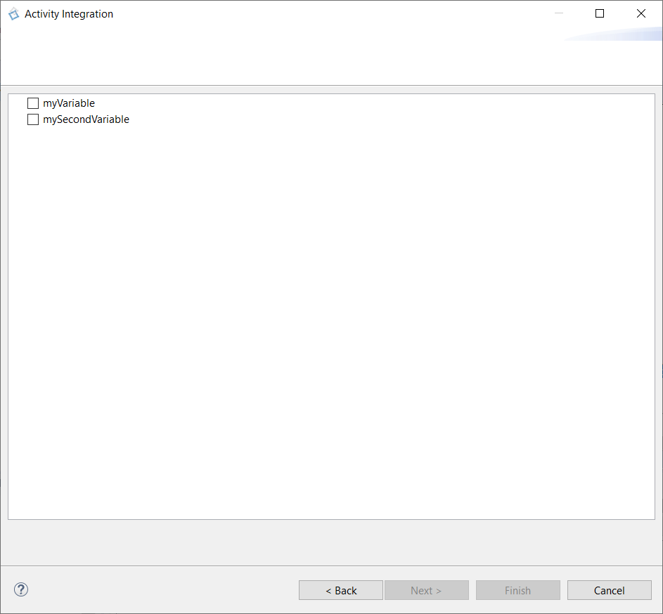
- By selecting "Set Default Values", you are able to set function's variables to their default values (that you defined at their creation). Click on "Next" to have the list of function's variables and select one or more:
You can click on "Finish" to terminate the implementaion, or you can click on "Next" to have more details on the variables you selected:
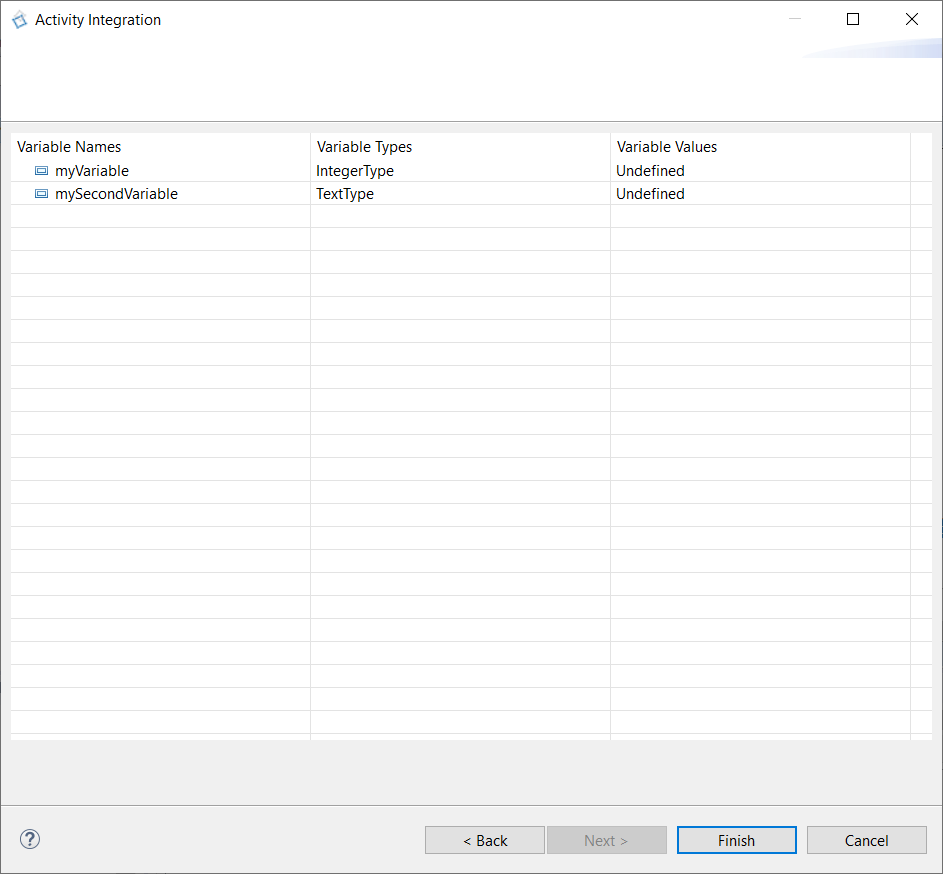
With the upper example, the activity body will be:

- Concerning "Matlab Model" and "Python Function", a specific section are dedicated to them to the next page.
The usage of Python function is only available in the version pro of Designer.
If you have to modify your code, right click on the activity and select Edit > Edit Body:

STATE MACHINE
As during the Project Definition, a State Machine is automatically created for each Technical Function, with a state "FirstState".
You have to define the other states.
Concerning the transitions, they will be generated automatically, by right clicking on Edit > Generate State Machines, on each sequence diagram., or by selecting a sequence diagram in the Overview and clicking on Generate StateMachine.
GENERATE CODE FROM TF STATE MACHINES
In order to switch the behavior of the generated code from the Service to the newly described functions, you need to do some changes in the model. If you don't, even if you finished the description of the technical functions, the code generated and simulated will be the service's. So you won't notice any change. Thus be careful to not forget to switch the behavior before generating the code.
Go back to Service tab in the Overview
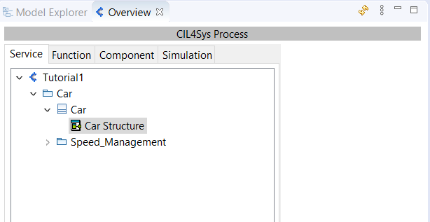
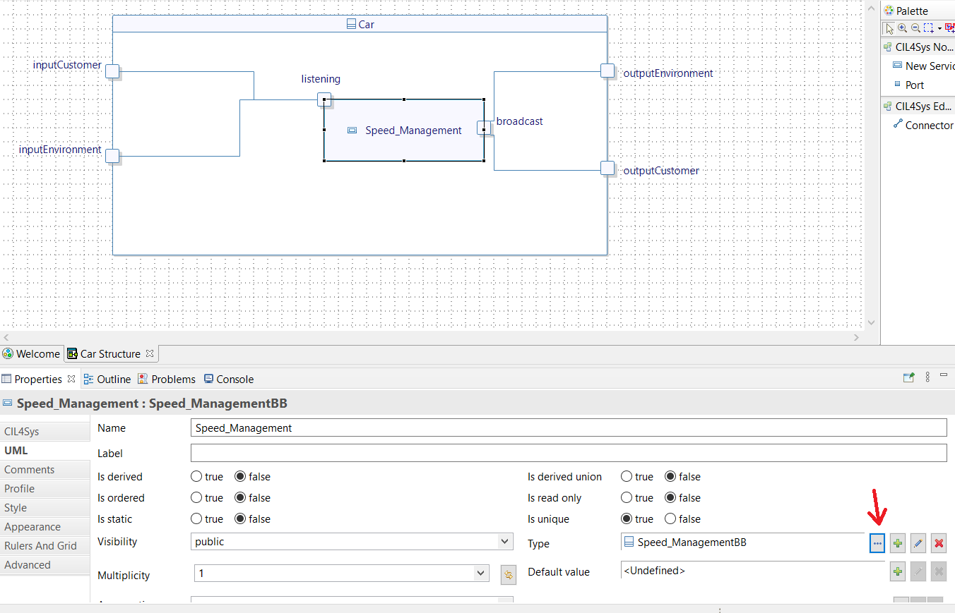
Open the structure diagram of the Product (Car)
Select the Service
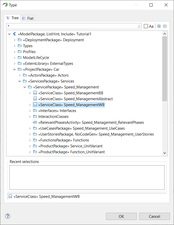
Highlight the Properties view and set the type of the service on Speed_ManagementWB (or name_of_the_serviceWB)
Come back to the function tab, so you don't forget to work on the right level of simulation.
If you want to go back to generating and simulating the behavior of the service and no more the function's, you can reverse the changes. You have to reopen the structure diagram of the product and chose the Black Box service (Speed_ManagementBB or name_of_the_serviceBB).