Generate State Machine transitions
After the Sequence Diagrams of the Service completed, we will summarize the defined states and transitions in a State Machine.
A State Machine inventories the different states that can have a Service, and also shows discrete behavior of a part of designed system through finite state transitions.
Each Service has a State Machine.
Before generating the state machine, make sure you have completed your Service Sequence Diagrams. After generating the state machine, you can proceed to code generation.
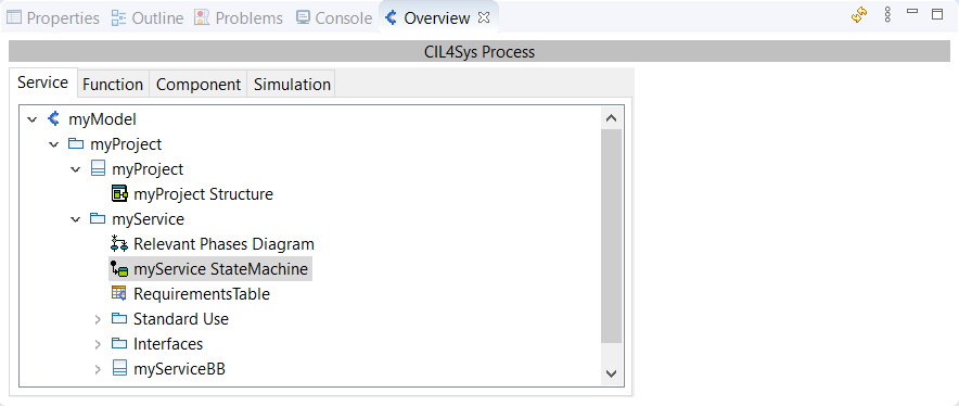
To access the State Machine Diagram of a Service, you have two ways:
- Double Click on a State in a Sequence Diagram
- Double Click on the Service StateMachine in the Overview:
CREATE THE STATES
At the beginning, a State Diagram is composed of three elements:
- An Initial State
- A state named "FirstState"
- An initial transition between the two former elements
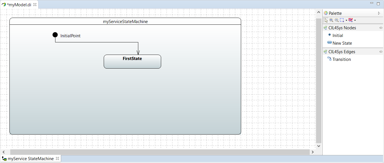
To rename a state, you just have to change its Name in Properties tab. Or right click on the State, select Edit > Rename State and tape the new name in the new pop-up.
To create additional states, Drag&Drop a New State inside the frame and name your state.
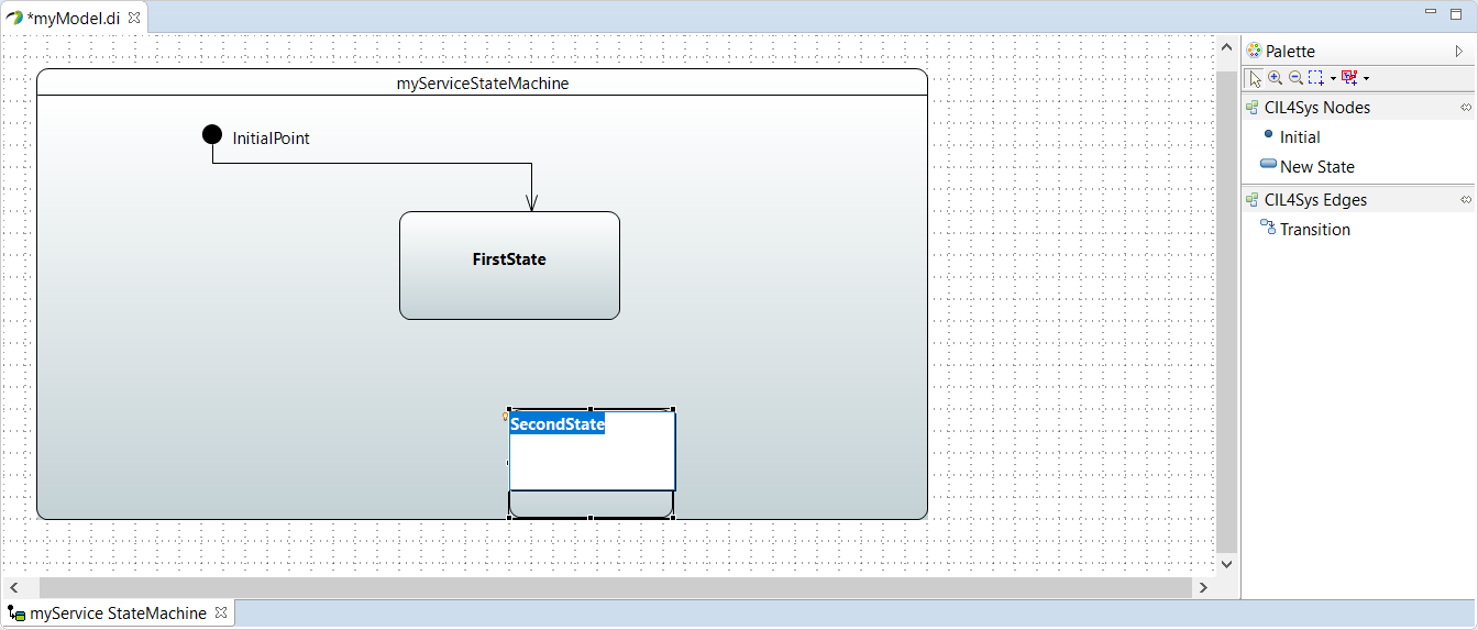
States can have three different types:
- Atomic:
It's the simplest state existing and the one by default:

- Sequential + Initial State (+Stereotype)
This type allows sub-states.
For example, inside a state "FirstState", we can have the states "SubState1" and "SubState2":
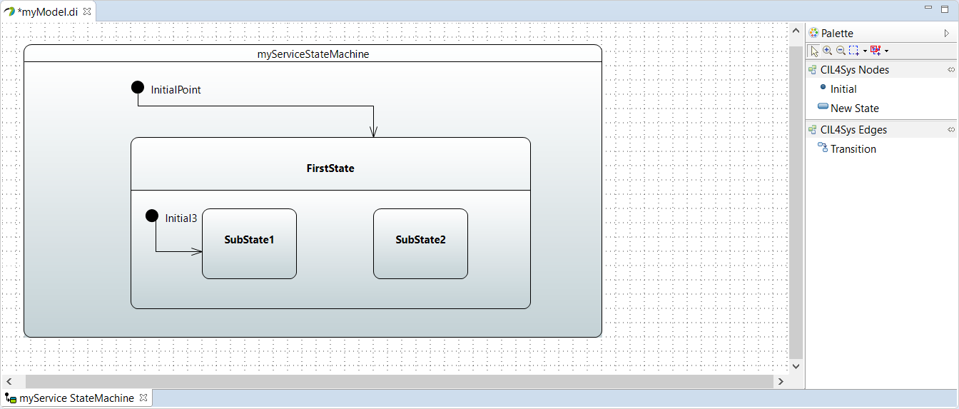
The UML standard requires us to define a default initial state, inside a Sequential State (in the upper example, we choose the state SubState1). To realize the creation, Drag&Drop a Initial point inside the lower part of the Sequential State. Then, trace the Transition from the Initial Point to the SubState.
To change automatically an Atomic State to a Sequential, Drag&Drop a New State inside its frame.
You can also do manually, by adding a region.
You can delete a region by right clicking in the region background, then Delete.
If your State Machine has only one region, you can also delete it, but you will BREAK your model!
- Concurrent:
This type allows to have two Sequential State inside the same state:
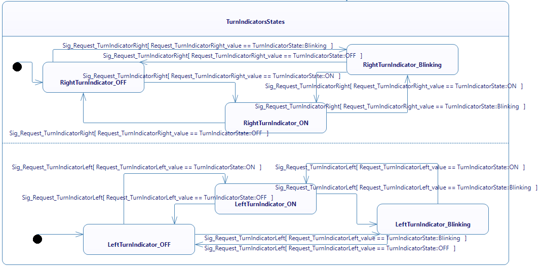
Inside the same state you can define as much region as you want to define your system. These region will describe one behavior of the system that can happen in the same time than the behaviors in other region. In the previous example we have two regions, one for "right indicator" and another for "left indicator". Since we wanted to make them have independant behaviors, one possibility of modeling is to describe them in two separate region. Thus they will behave separately.
You might have compiling errors in current version of Papyrus Designer. To rectify this, you only have to suppress all the lines with an orphan "true" and rebuild your code.
void serviceBB::processCompletionEvent() {
	systemState = statemachine::SystemStateEnum_t::EVENT_PROCESSING;
	if (systemState == statemachine::SystemStateEnum_t::EVENT_PROCESSING && (currentEvent->associatedState == activeStateID)) {
		switch(activeStateID) {
			case STATE4_ID:
				//from State4 to TurnIndicatorsStates
				if (true) {
				activeStateID = TURNINDICATORSSTATES_ID;
				//starting the counters for time events
				true
				//TurnIndicatorsStates_Region1_Enter(TURNINDICATORSSTATES_REGION1_DEFAULT);
				pthread_t TurnIndicatorsStates_Region1_enter_thread;
				statemachine::StructForThread_t TurnIndicatorsStates_Region1_enter_thread_struct(this, REGION_ID_TURNINDICATORSSTATES_REGION1, TURNINDICATORSSTATES_REGION1_DEFAULT, statemachine::ThreadFunctions::TF_ENTER_REGION, 0);
				serviceBB_THREAD_CREATE(TurnIndicatorsStates_Region1_enter_thread, TurnIndicatorsStates_Region1_enter_thread_struct)
				true
				//TurnIndicatorsStates_Region2_Enter(TURNINDICATORSSTATES_REGION2_DEFAULT);
				pthread_t TurnIndicatorsStates_Region2_enter_thread;
				statemachine::StructForThread_t TurnIndicatorsStates_Region2_enter_thread_struct(this, REGION_ID_TURNINDICATORSSTATES_REGION2, TURNINDICATORSSTATES_REGION2_DEFAULT, statemachine::ThreadFunctions::TF_ENTER_REGION, 0);
				serviceBB_THREAD_CREATE(TurnIndicatorsStates_Region2_enter_thread, TurnIndicatorsStates_Region2_enter_thread_struct)
				pthread_join(TurnIndicatorsStates_Region1_enter_thread, NULL);
				pthread_join(TurnIndicatorsStates_Region2_enter_thread, NULL);
				systemState = statemachine::SystemStateEnum_t::EVENT_CONSUMED;
				}
				break;
			default:
				//do nothing
				break;
		}
	}
}
Here the two "true" after "if(true)" are false. You can delete them. Be cautious that they will reappear each time you regenerate the model.
GENERATE THE TRANSITIONS
The transitions of a State Machine are created from Sequence Diagram(s), by right clicking on the sequence diagram, and selecting "Edit > Generate State Machines":

Or, by clicking on "Generate StateMachine" button in the Overview:
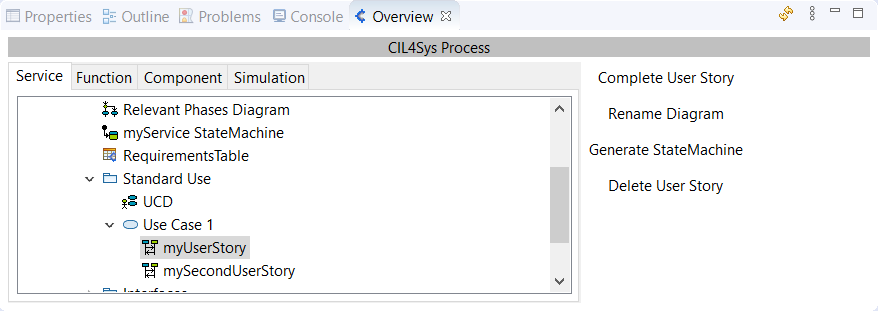
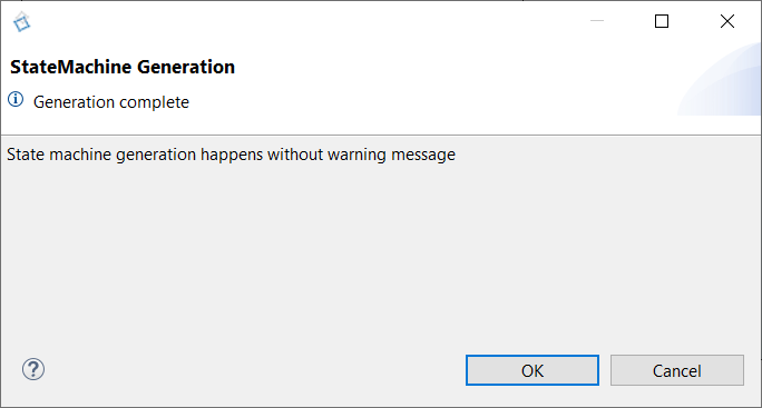
You will be informed when the generation finished by a pop-up:
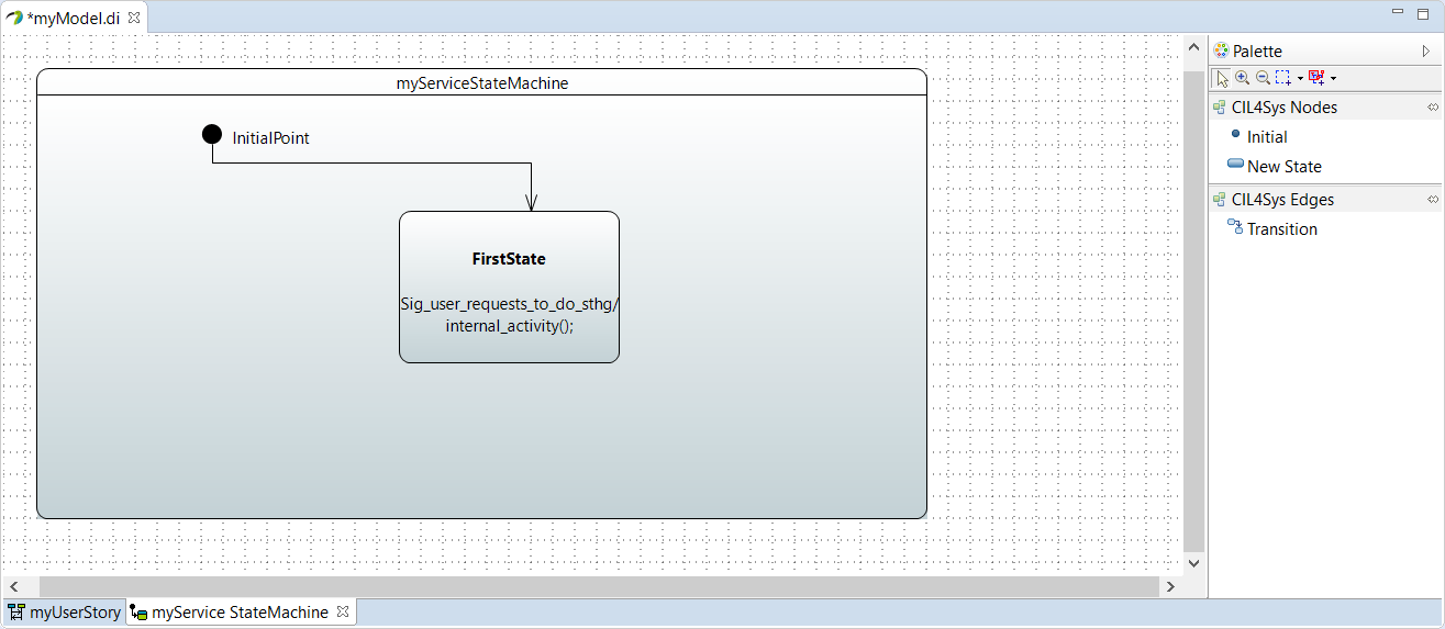
The State Machine generated looks like this:
On the Overview side, you will also find your transition in a branch of the Sequence Diagram:
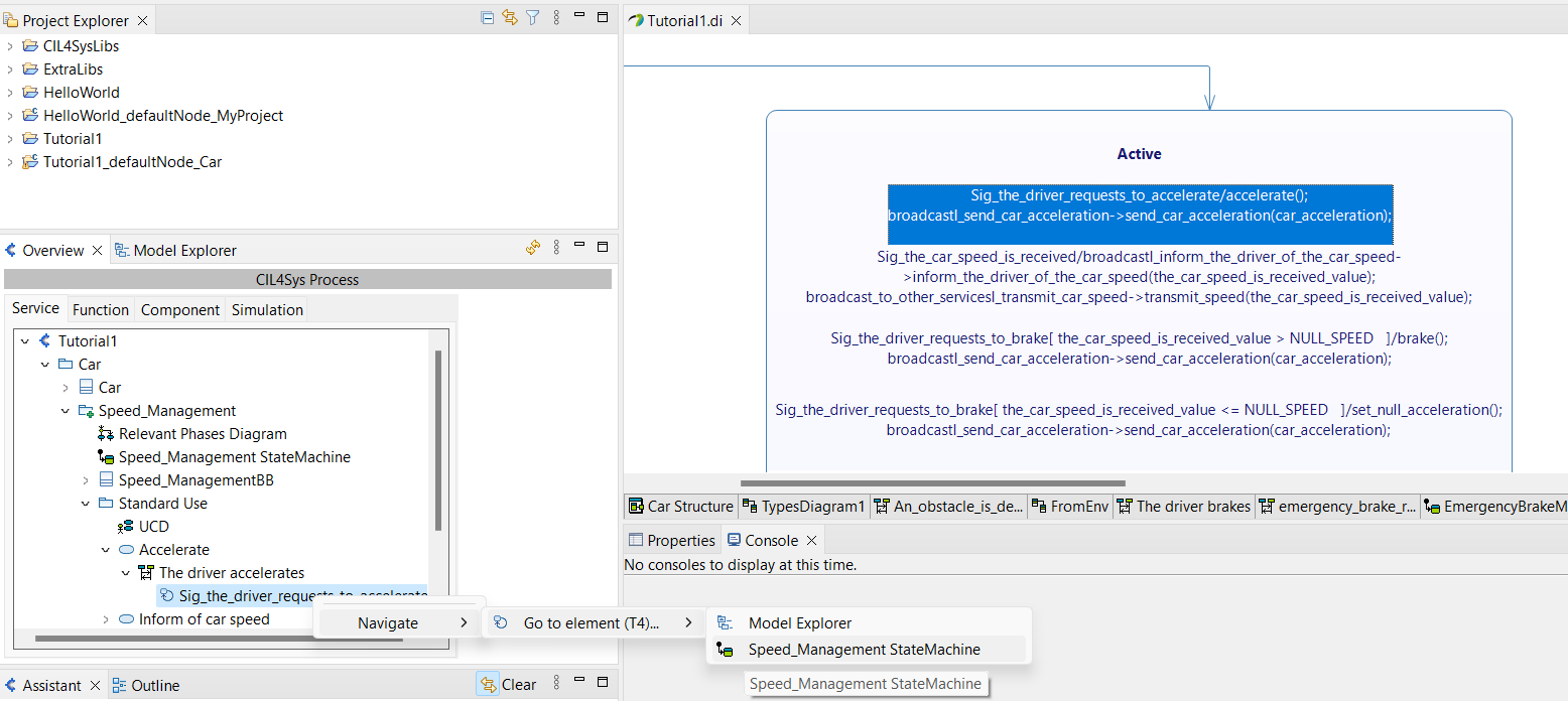
This transition whose the name generally starts by Sig for "Signal" is mapped into the correponding state machine :
To locate it in the state machine, right-click on the transition > Navigate > Go to element > the associated state machine
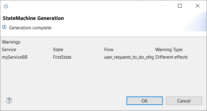
If you have two or more transitions with the same trigger flow and the same Guard Condition, but different activities after, the software will alert you with the below message, but the transitions will be generated:
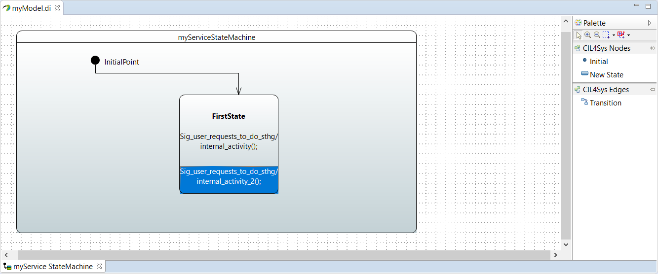
If a transition which is exactly the same that the one you are generation, already exist, the software will concatenate them.
In case of the concatenation is a mistake (trigger flow and/or conditions), you must delete one of the trigger flow to recreate another requirement.
Double Click on a transition opens the Sequence Diagram that generated it.
To delete a transition from a State Machine, you must delete the trigger in the corresponding Sequence Diagram (the Guard Condition related will be deleted at the same time). The State Machine will be up to date.
FIND NON EXCLUSIVE REQUIREMENTS
Work in progress