New Use Case
We create use cases to indicate the interactions between actors and life situations of the system. In other words, how the actors will use the system.
The actor represents an external element that interacts with the system. This element can be a user or a third party system (other computer, other program, database, etc.).
CREATE A SIMPLE USE CASE
Creation
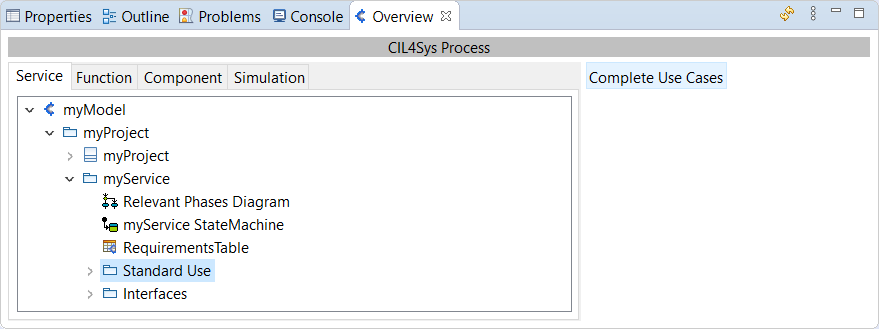
Use Cases are created in a Use Cases Diagram, which is opened by selecting the Life Line and clicking on "Complete Use Cases":
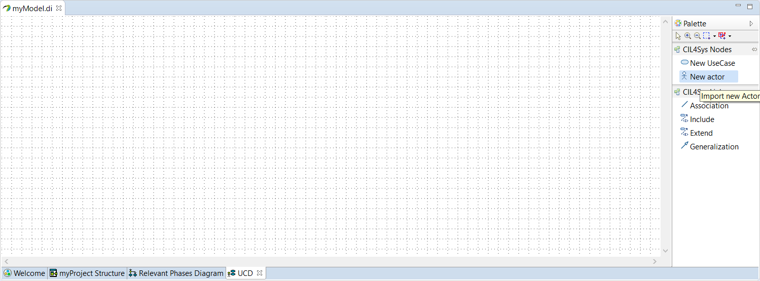
Drag&Drop an actor on the diagram:
Select User and click on OK:
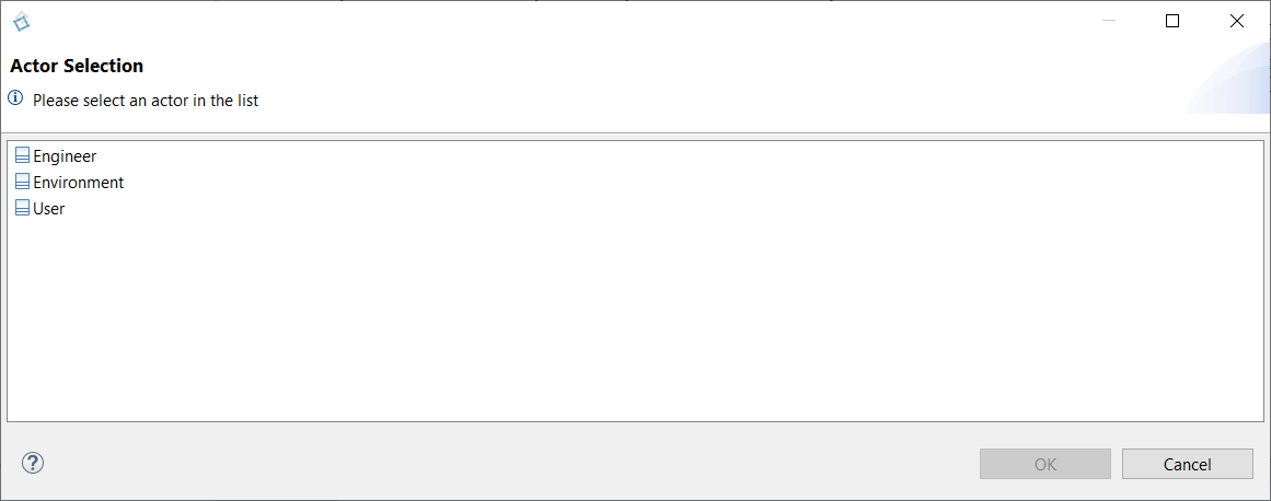
We can differentiate 3 types of actors in the Sim4Sys models.
The User actor represents a person who interacts with the system being modeled. For example, for a car, the driver is a User type actor.
The Engineer actor represents an engineer who would like to modify an internal value of the system. Engineer's flows do not appear in specification documents.
The Environment actor represents all other actors that are not an User or an Engineer type. For instance, in the Car system, the street would be an Environment actor.
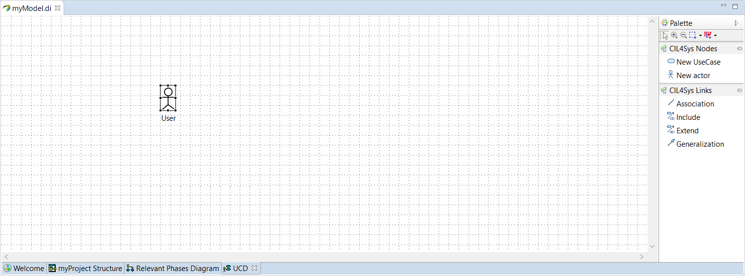
Drag&Drop a New UseCase on the diagram, type the name of the use case and click on OK:
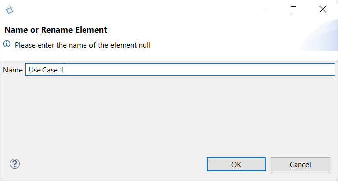
Naming rule: Use Case naming consist on a verb conjugated in the present tense, followed by complements (ex: Drive, Brake, Accelerate…). They are redacted from the actor's point of view.
Use this magic sentence: "The [actor name] uses the [system name] to [use case name].
If, by replacing the sections in this sentence with your names, this one is clear, then you have chosen your words correctly.
Now, you can associate the actor and the use case by tracing an association:
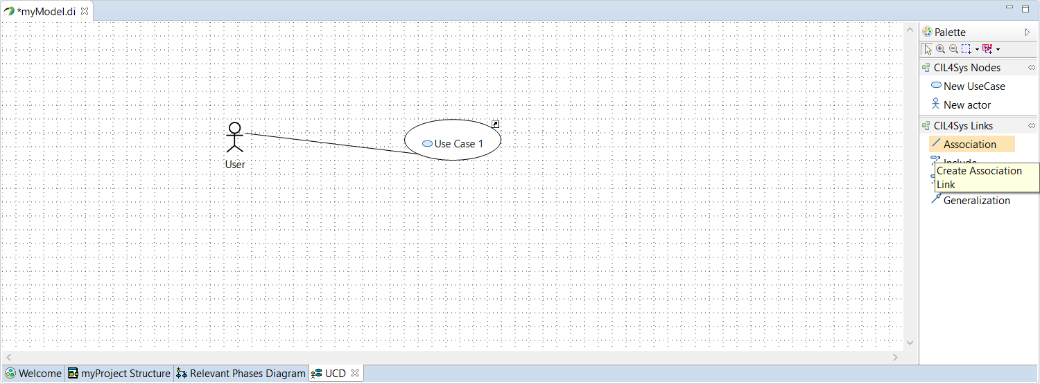
Association
Work in progress
By default, a Use Case is related to the Life Phase in which it is created, but it could be possible that a Use Case is common to various Life Phases. This information should be completed in the Life Phase's Properties, in tab "CIL4Sys", line "Associated use cases" and "Add elements":

Select the Use Cases to associate via the below window:
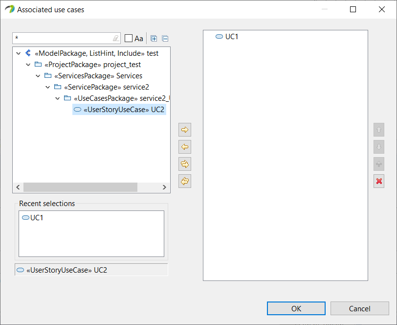
Push the wanted Use Case with the arrows and click on OK.
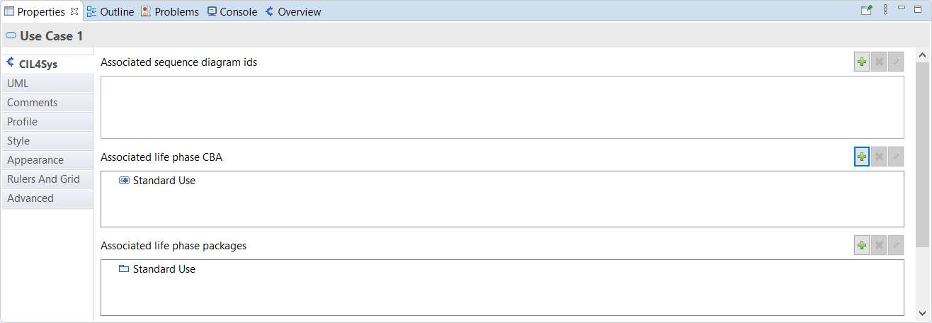
On the Use Case side, you have to do a similar way with "Associated life phase CBA" and "Associated life phase packages":
Rename a Use Case
You are able to rename a Use Case via its Properties > UML > name:

Delete a Use Case
You can delete a Use Case by right click "Delete Selected Element" (or with key Delete):
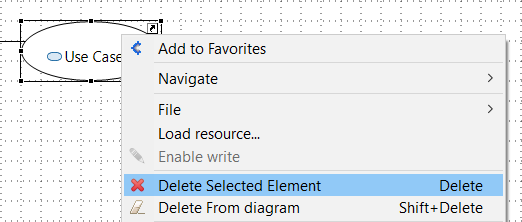
The Use Case will be deleted, but the associated User Stories will not be deleted.
RELATIONSHIP BETWEEN USE CASES
Many dependency relationships can be defined between use cases through the use of stereotypes.
Include relationship
- Added by clicking on

"The Include relationship is intended to be used when there are common parts of the behavior of two or more Use Cases. This common part is then extracted to a separate Use Case, to be included by all the base Use Cases having this part in common. As the primary use of the Include relationship is for reuse of common parts, what is left in a base Use Case is usually not complete in itself but dependent on the included parts to be meaningful.
All of the behavior of the included Use Case is executed at a single location in the included Use Case before execution of the including Use Case is resumed. The Include relationship allows hierarchical composition of Use Cases as well as reuse of Use Cases." (UML 2.5)
The source use case always contains the included use case.
Example: Use Case A includes Use Case B

Can be seen as:
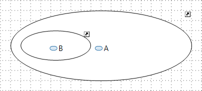
Included Use Cases are necessarily present in the same service than the including Use Case.
Extend relationship
- Added by clicking on

"Extend is intended to be used when there is some additional behavior that should be added, possibly conditionally, to the behavior defined in one or more Use Cases.
The extended Use Case is defined independently of the extending Use Case and is meaningful independently of the extending Use Case. On the other hand, the extending Use Case typically defines behavior that may not necessarily be meaningful by itself. Instead, the extending Use Case defines a set of modular behavior increments that augment an execution of the extended Use Case under specific conditions." (UML 2.5)
The source use case is not always necessary in the primary use case.
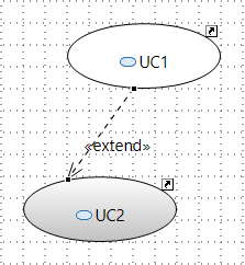
Example: Use Case B extends Use Case A

Extended Use Cases can be present in a different Service than the extending Use Case.
Example:If a Use Case 2 from another service has an impact on the service we want to specify, we add it on the diagram by drag & dropping from Model Explorer and it will appear in the diagram, but it will not be associated to the Life Phase and Use Case Diagram.
For a better representation, you can change the background color by right click and select Format > Fill color.
