Executables Definition
This page covers the management of executables in your project, detailing how to add, configure, and utilize executables, including the integration of model parts and mappings.
To generate an executable from Sim4Sys-Designer code, see Code generation for Community version or Code of the State Machine for Pro version. After importing types and flows, you can create mappings as described in Mapping model to simu.
Executables
Add an executable
This section outlines how executables are managed within the project, providing the means to integrate and configure them as required for visualizations or other purposes.
The list of executables currently included in the project is displayed here:

To introduce a new executable into the project, click on the “add executable” button: 
This action will prompt a pop-up where you can specify the name and the location path of the new executable:

Upon creation, the new executable will be listed among the existing executables:

For each executable within the list, you have several options:
- To rename the executable, click on the "Configure executable" button:

- To import an XML file generated by the model, use the "Import types and flows" button:

- If the executable is not currently in use, it can be deleted by clicking on the "Delete executable" button:

- To view details about the executable, click on the "Information button":

Ensure that the location path of the executable is accurately entered to facilitate its proper use within the project. Should the need arise to adjust the executable's location path or other details, you can reconfigure it accordingly.
Reconfigure executable
Configuring and importing data for executables within your project involves several steps, allowing you to fine-tune how your visualizations interact with external programs or scripts.
Configuring an Executable
To adjust the settings of an executable, including its name and location, click on the "Configure executable" button:  . This action opens the configuration pop-up:

Here, you can rename the executable and specify its location path, ensuring it correctly points to the executable file you intend to use.
Importing Types and Flows
To import types and flows from an XML file, click on the "Import types and flows" button:  . This will present you with a file selection interface:
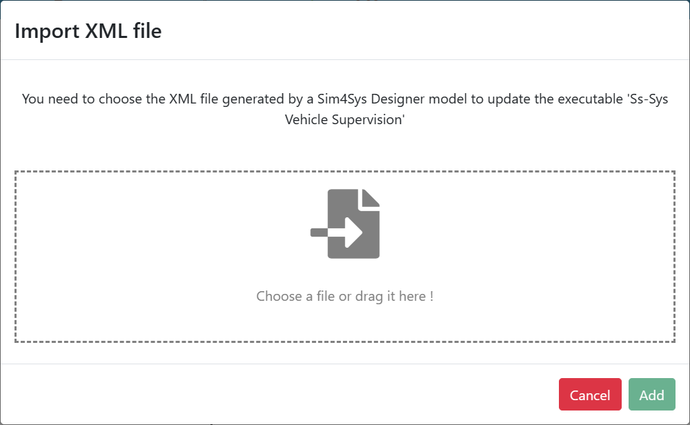
You can either drag and drop the XML file into the designated area or browse your computer to select it.
If the source of your XML is different from the previous one, a warning message will be displayed. Click OK to continue:
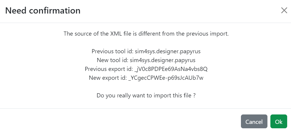
After adding the file, you will be provided with a summary of the importation process:
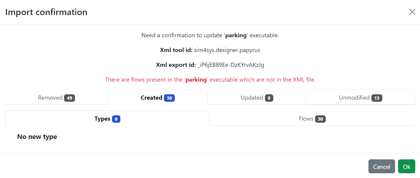
Review the summary, and if everything appears as expected, click "Ok" to finalize the import. If you need to make adjustments, click "Cancel" to abort the process.
Flows that have been removed from the model are categorized in the summary as either Used (for those with mapping instances still in use) or Not used (for those without mapping instances used in any scenario). The “Removed” category contains the names of deleted flows to easily identify them.
Following the import, the newly added types and flows will be listed, ready for integration into your project's visualizations:
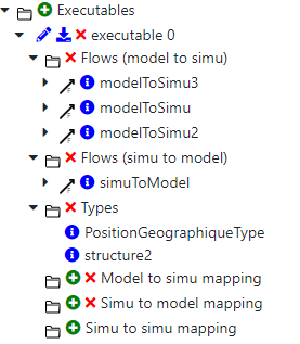
This process ensures your project's executables are correctly configured and aligned with the latest model definitions, enhancing the accuracy and relevance of your visualizations.
If you have made any changes to your flows, you will be able to see these changes in “Updated” --> “Flows”, you'll be notified of any changes that have been made, whether to the name of a flow or to the name of a parameter.
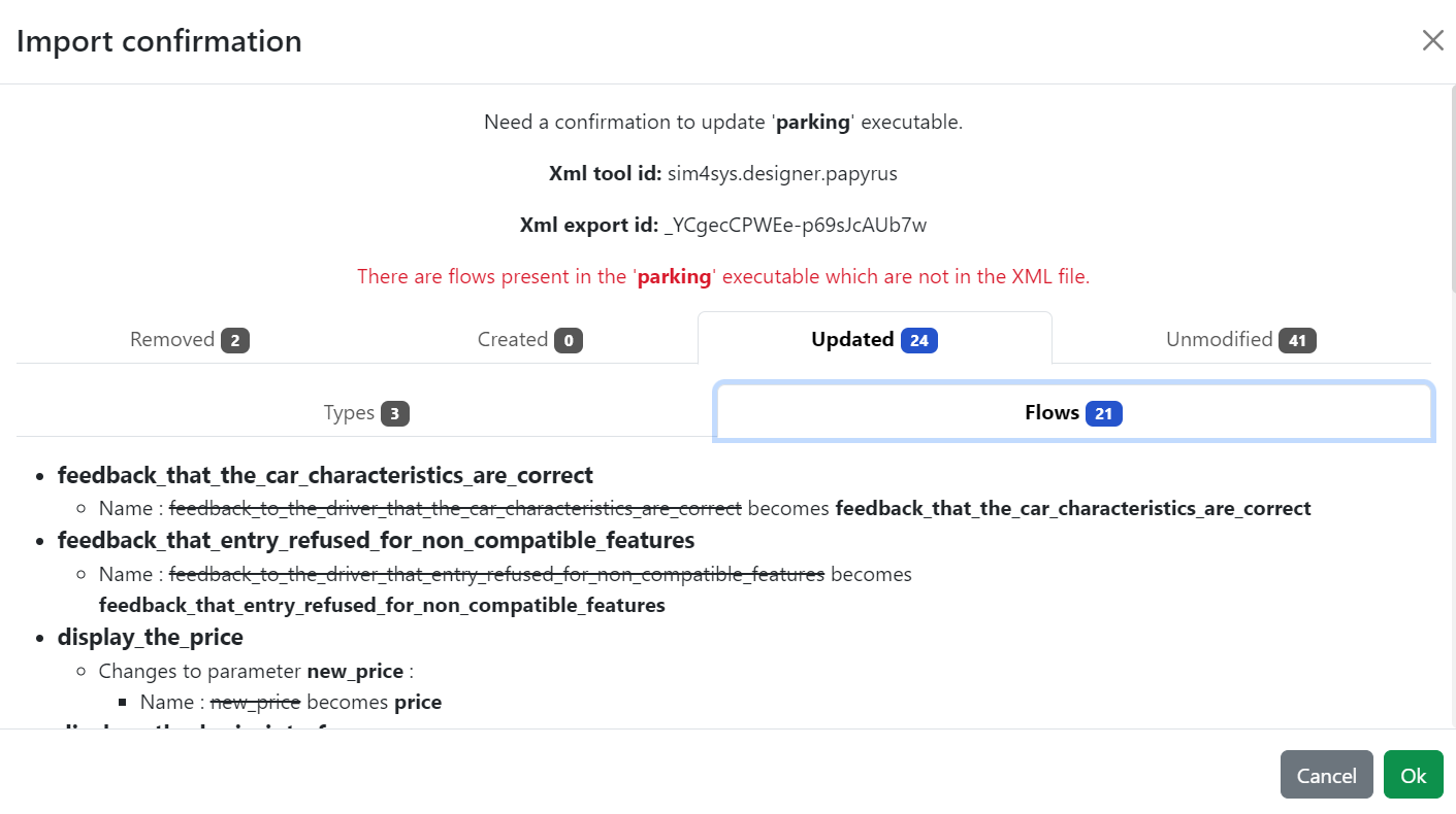
Actions available on imported flows
By selecting the "See description" button:  , you're given insight into the specific details of a flow as defined within the UML model. This comprehensive view includes:

The information displayed encompasses:
- Flow Name: The identifier for the flow.
- Actor: Identifies who or what initiates or interacts with the flow. Possible actors include a user, the environment, or an engineer.
- Direction: Specifies the flow's direction, which could be from the model to the visualization (modelToSimu) or from the visualization to the model (simuToModel).
- Number of Parameters: Indicates how many parameters are associated with this flow.
- Name and Type of Each Parameter: Provides a detailed listing of each parameter's name and data type.
- Mapping Summary: Offers an overview of how the flow's parameters are mapped, which is crucial for understanding how data is exchanged or transformed within the visualization context.
This detailed overview allows for a deeper understanding of how specific flows are designed to operate within your project's visualizations, based on their original UML model specifications. This can aid in troubleshooting, optimizing, or expanding the functionality of your visualizations.
Executable information
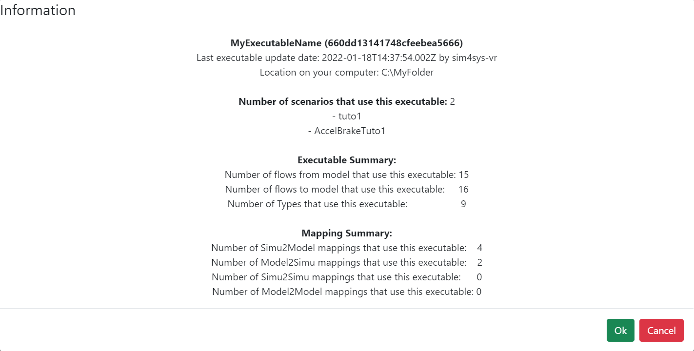
Clicking on the "Executable information" button brings up a pop-up window that provides comprehensive details about the executable, facilitating better understanding and management within your project. The information presented includes:
- Executable Name: The name assigned to the executable.
- Tool Id: Identifies the tool used to generate the imported XML, assisting in tracking the source of your executable configurations.
- XML's Export Id: A unique identifier for the XML export, allowing for version control and identification of changes.
- Last Update Date: The date the executable or its configurations were last updated, along with the ID of the updater.
- Location on Your Computer: The file path to the executable as defined in the executable configuration pop-up, ensuring you can locate and access the executable directly if needed.
- Number of Scenarios Using This Executable: Lists how many scenarios within the project utilize this executable and provides a list of these scenarios for quick reference.
- Executable Summary: Offers a snapshot of the executable's integration within the visualization, including:
- The number of flows from the model to the visualization.
- The number of flows to the model from the visualization.
- The total number of Types defined within the executable.
- Mapping Summary: Details the extent of mapping configurations established for the executable, breaking down into:
- The number of Simu2Model mappings.
- The number of Model2Simu mappings.
- The number of Simu2Simu mappings.
- The number of Model2Model mappings.
The Tool Id and Export Id play critical roles in maintaining the integrity of your project’s data. They ensure that when uploading XML files, the system can verify whether the incoming data matches the existing configurations or if there are discrepancies. In cases where differences are detected, Virtual Bench will prompt for confirmation, as shown:
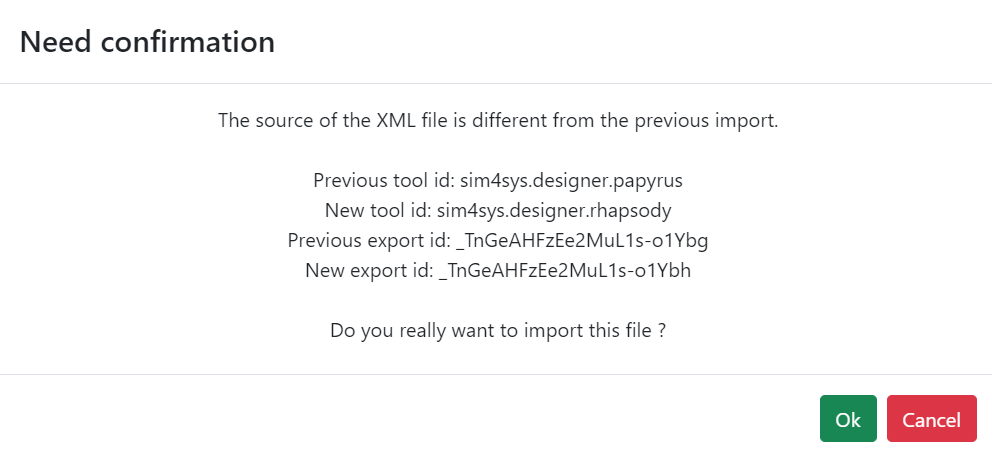
This detailed overview allows project managers and team members to maintain a high level of control over the executables used in visualizations, ensuring they are up-to-date and correctly integrated within the project's framework.
Delete executable
When you decide to remove an executable from your project by clicking on the "Delete executable" button, the system will proceed based on whether the executable is currently in use within any of the project's scenarios:
- Executable Not in Use: If the executable is not being used by any scenario, it will be successfully removed from the project. This action is confirmed by a notification:

- Executable in Use: Conversely, if the executable is linked to one or more scenarios, the system will alert you that removing the executable is not possible due to its active integration within the project:
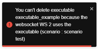
This mechanism ensures that critical components of your project's visualizations are not inadvertently deleted, maintaining the integrity and functionality of your visualizations. It provides a safeguard against the loss of important data or configurations that could impact the project's outcomes.
Element creation mapping
In your project's specified folder, you'll find element creation mappings. These mappings enable the dynamic instantiation of visualization objects during visualization runs, enhancing the visualization's flexibility and responsiveness to various conditions or events.
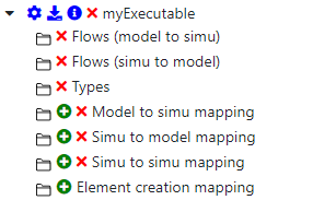
This feature is vital for visualizations that require the introduction of objects on-the-fly, allowing for a more detailed and adaptable visualization environment.
Model Parts
This section will describe model parts. A model part is linked to a designer executable that defines a system model. A model part represents a part of a model, such as a system, a function, or a system component, but also actors or environment.
You can import model parts from a CSV file with the button :

You should generate the CSV in Designer with the option Generate Interface Summary File. You will need to import each CSV generated by each interface or concatenate all the CSV in one (with the column title appearing only once) and import this file.
-
See documentation on the generation of Interface Summary File here.
-
Virtual Bench can not attribute the "environment" as a model part source or a model part target. You will have to create and assign it manually for the concerned flows.
Also, you can set model parts manually by clicking on the add button.

Parameters to fill:
| parameter | description | Required | Unique |
|---|---|---|---|
| Name | Name of the model part you want to create | ✔️ | ✔️ |
| Color | The color that will represent the model part (Parameter saved but not implemented yet, will be useful in the next releases) | ✔️ | ❌ |
| Type | Type of the model part (explained below) | ✔️ | ❌ |
| Model Part Link | Other internal model parts available in other executables (model). It is useful for scenarios with multiple system exchanges. (Only available when type is Other Model) | ❌ | ❌ |
Type explaination:
| Litteral Enumeration | Description |
|---|---|
| Internal | Represent a part included in your designer model. It can be the global system, allocated functions, system components, ... |
| External | Represent a part that is extern to the designer model but which is not represented by another internal model part in the VB project. It can be actors, users, the environnement, ... |
| Other Model | Represent a part that is extern to the designer model and is represented by another model part in the VB project. When selected you must specify the linked other model part. |
Flow Configurations
After completing the creation of your model parts, the next step is to configure executable flows within your project. This process involves specifying the origin (source) and destination (target) for each flow. A unique feature is the ability for a single flow to be associated with multiple model parts, either as a sender or receiver. To do this, simply select the appropriate model parts for each flow.

Future updates will introduce automatic synchronization of model parts and flow definitions directly from the model, enhancing efficiency and accuracy. Despite this automation, users will retain the capability to manually adjust these configurations to suit their specific needs.
Executable details information
Clicking on the "Information" button for an executable within your project reveals a pop-up that offers a detailed summary of the executable's configuration and usage. This includes:
- Name and ID: Identifies the executable along with a unique identifier.
- Last Executable Update Date and Author: Shows when the executable was last updated and who made the changes.
- Location on Your Computer: Provides the file path to where the executable is stored on your system.
- Number and Names of Scenarios Using This Executable: Lists how many and which specific scenarios within the project utilize this executable.
- Number of Flows From Model: Indicates the quantity of data flows originating from the model to the visualization.
- Number of Flows To Model: Shows the number of data flows from the visualization back to the model.
- Number of Types: The total number of unique data types used within the executable's configuration.
- Number of Simu2Model Mappings: The count of mappings that transfer visualization outputs to model inputs.
- Number of Model2Simu Mappings: The count of mappings from model outputs to visualization inputs.
- Number of Simu2Simu Mappings: The number of internal visualization data mappings.
- Number of Model2Model Mappings: The count of direct model-to-model data mappings.
This comprehensive overview assists in managing and understanding the integration of executables within your project, providing key insights into their application and impact on visualizations.
Model to Model Mappings
In your project, you'll find a section dedicated to Model to Model mappings. These mappings are crucial for defining how data is transferred and transformed between different parts of the model within your visualization environment.
For more comprehensive details, including how to create, edit, and manage these mappings, refer to the Mapping page. This resource provides in-depth guidance on leveraging Model to Model mappings to enhance the accuracy and efficiency of your visualizations by ensuring seamless data flow and integration between model components.